Ezurio’s Vela IF820 Repurposed: A Step-by-Step BTstack Development Board Setup
Once testing on Linux, macOS, or Windows is complete — and if there are no plans to run BTstack directly on an SoC — the next challenge is usually connecting an MCU development kit to a Bluetooth Controller breakout board via the Bluetooth UART HCI interface, and getting the stack up and running on the MCU. While BTstack can be ported to almost any MCU/development kit, the process involves figuring out the correct UART pinout and carefully adding jumper wires between the boards. No matter how carefully this is done, the result will be a fragile setup that’s inconvenient to transport or use for demonstrations.
In this post, we show how we repurposed a standard Bluetooth Controller breakout board into a dedicated BTstack development board by reusing its onboard MCU originally used to bridge the Bluetooth UART HCI interface to USB CDC.
The breakout board in question is Vela IF820 Development Kit from Ezurio, which features Infineon’s AIROC CYW20820 – so far their latest dual-mode Bluetooth Controller with support for LE Data Length Extension and 2M-PHY. To handle USB-to-UART conversion and provide an SWD programmer, Ezurio integrates a Raspberry Pi Pico RP2040 running Raspberry Pi’s DebugProbe, previously known as Picoprobe. The RP2040 is both affordable and capable enough to run our stack, enabling us to compile all examples for this setup and flash them directly onto it without any modifications to the breakout board.
Ready to see it in action? In the following sections, we take you step-by-step through porting BTstack onto the Vela IF820. The challenges we encountered are mostly universal, so even if you don’t plan to use this board, you’ll find useful insights here. We finish by measuring SPP (Classic) as well as GATT Notification (LE) throughput — a simple but effective way to verify that everything is working properly.
Recon
With the goal set, let’s have a look on the Vela IF820 board and try to identify what we got there.
The main components obviously are the RP2040 and the CYW20820. While we could have used a multimeter and tried to figure out how the CYW20820 is connected to the RP2040, we’ve instead asked our partner Ezurio and they kindly provided us with the following information:
| Pin | Function |
|---|---|
| GPIO00 | BT_UART_RX |
| GPIO01 | BT_UART_TX |
| GPIO02 | BT_UART_RTS |
| GPIO03 | BT_UART_CTS |
| GPIO13 | RST_L |
There’s also an RGB-LED connected to the RP2040, but we ignored it. As it seems to be similar to the popular WS2812, we leave it to the motivated reader to make use of it when needed 🙂
With that mapping, the next steps are:
- Flash an HCI Firmware on the CYW20820 to convert it into a regular Bluetooth Controller
- Power cycle the CYW20820 to get it into a known state
- Configure RP2040 UART
- Test sending HCI Reset and getting the expected response
- Implement the full UART driver and bring up the whole stack
Turn SoC into regular Bluetooth Controller
In contrast to most other Infineon AIROC Controllers, the CYW20820 contains flash memory and is intended to be used as an SoC. For this, Infineon provides ModusToolbox – an Eclipse-based IDE with support for their SoC – to develop your own application based on their SDK. As with all Infineon Controllers that contain flash memory, it’s possible to convert them into a pure Bluetooth Controller with HCI UART interface by flashing the empty application example from ModusToolbox.
In the case of the Vela IF820, Ezurio provides a ready-made firmware that contains module-specific modifications that configures the HCI UART to 3 mbps. Excellent! As there’s no need from our side to modify that, we follow Ezurio’s instruction to load their HCI firmware version onto the module.
Reset Bluetooth Controller
To bring the Bluetooth Controller into a known state, we need to power cycle the CYW20820 by toggling RST_L line. For this, we configured GPIO13 of the RP2040 and implemented a typical power cycle:
- set RST_L low
- wait 100 ms
- set RST_L high
- wait 100 ms
Easy, no?
When connecting the logic analyzer to RST_L, we expected a line that goes low for 100 ms before going up again. However, we got this unexpected trace:
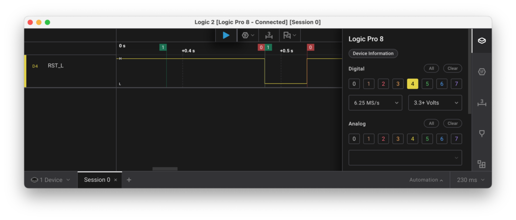
The trace seems to indicate that our “wait 100ms” only takes about 43 ms, which is rather odd.
As we are using the offical pico-sdk from Raspberry Pi, we expected the timing to be roughly correct. To analyze this, we’ve configured GPIO21 as test pin and toggled that together with GPIO13 to get this:
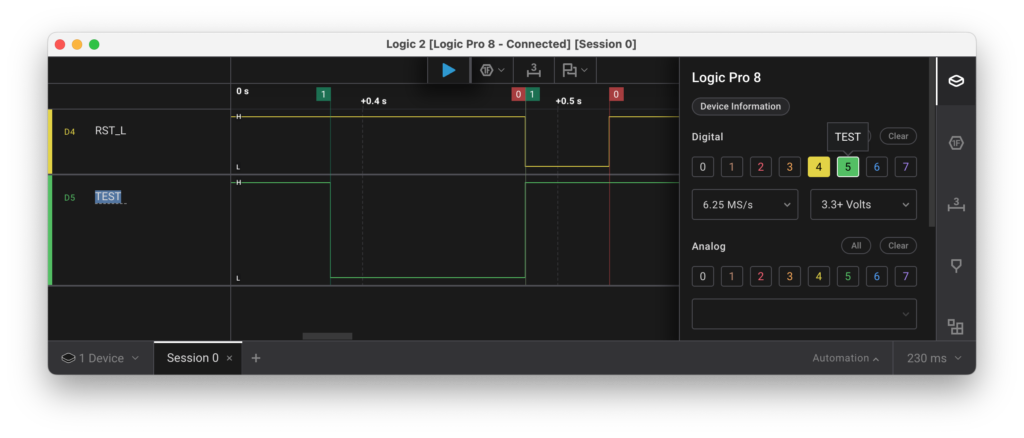
The trace shows that RST_L goes low only after GPIO13/GPIO21 has gone high again and then stays low for about 43ms. Going back to the board, we identified a chip between GPIO13 and RST_L which is responsible for the fixed 43 ms low of the RST_L line. We assume that this chip is used to provide a well-defined reset pulse after power gets supplied to the board.
Knowing this, we’ve updated the code to just pull GPIO13 low for 10 ms and then wait for the actual 43 ms pulse to power cycle the Controller before moving on.
UART on RP2040
As the CYW20820 provides an HCI UART interface, we use BTstack’s hci_transport_h4.c implementation, which handles the framing and parsing of HCI packets over a serial connection like a UART. hci_transport_h4.c in turn requires an instance of btstack_uart.h to send and receive blocks of data to the Controller.
As most embedded UART interfaces are asynchronous, e.g. they often provide the option to specify a data sent or data received callback, which might be called from interrupt context, we select btstack_uart_block_embedded.c for the btstack_uart.h interface, which can handle data sent / data received callbacks from interrupt context and only requires to implement hal_uart_dma.h. A picture better shows this configuration.
To implement read / write operation over an UART, most MCUs support three modes:
- Polling: the code sends / receives individual bytes in a loop and waits until all are processed.
- IRQ: an interrupt service routine (ISR) sends / receives the next byte, which allows for an asynchronous implementation that allows the main code to continue running.
- DMA: a DMA transfer sends/receive a block of data and triggers an interrupt on transfer complete, which also provides an asynchronous implementation.
The RP2040 uses ARM’s PrimeCell UART (PL011) with support for hardware flowcontrol (RTS/CTS) and a 32-byte FIFO buffer. Uncertain about the usefulness of the FIFO, we configure the UART to enable hardware flowcontrol but disable the FIFO to keep things simple.
First test using polling
Although polling cannot be used in an actual port as hal_uart_dma.h as requires an asynchronous implementation, we start with polling as the Pico SDK provides convenient uart_write_blocking and uart_getc functions that allow us to quickly verify that the CYW20820 responds to HCI Reset Command with the expected HCI Command Complete Event event.
Single-byte IRQ
Next, we try to switch to an interrupt-based implementation. The general idea for such an UART TX driver is to:
- store a pointer and length for the data to send
- enable UART TX Ready interrupt – called
UARTTXINTRby ARM - whenever the UART TX is ready, the IRQ is called
- in the UART ISR, the next byte is sent by writing to the UART TX register
- if this was the last byte, disable the IRQ and notify the application
After implementing this scheme, we gave it a try and… nothing happened.
Going back to the RP2040 Datasheet, Raspberry Pi respectively ARM left this note: “The transmit interrupt is based on a transition through a level, rather than on the level itself. When the interrupt and the UART is enabled before any data is written to the transmit FIFO the interrupt is not set. The interrupt is only set, after written data leaves the single location of the transmit FIFO and it becomes empty.”
So, the Interrupt works similar to other MCUs, but with the subtile difference that it doesn’t fire before the first byte has been written to the UART TX register. While annoying, we add a flag to track if we have sent at least one byte to the UART TX register and manually write the first byte to it.
Similar to the logic for sending data TX, we also implement the logic to receive data in the ISR. As that’s rather simple code and we have hardware flow control, we are rather surprised when we only receive parts of the expected HCI Command Complete Event which would be: `0x04 0x0e 0x04 0x01 0x03 0x0c 0x00.
The logic analyzer shows this:
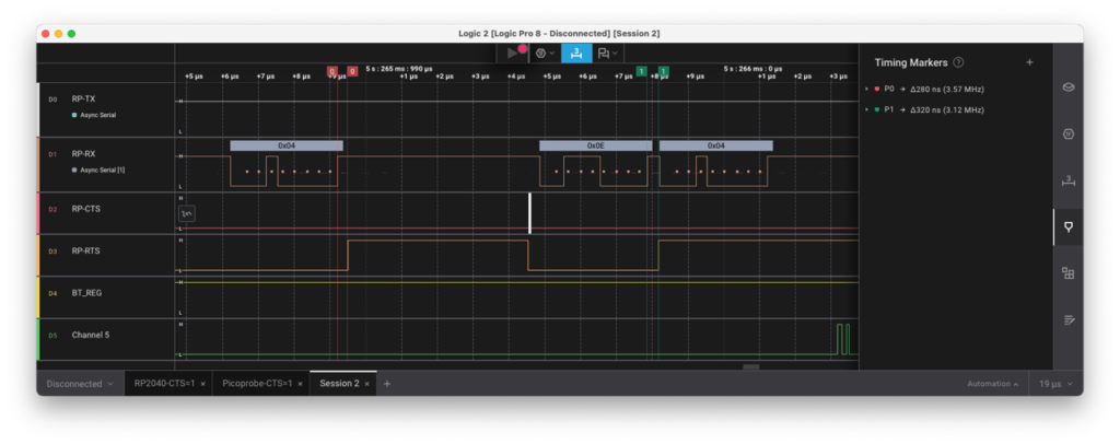
While RTS raises correctly after the first 0x04 byte and the CYW20820 pauses sending, RTS goes up a tiny bit later after receiving the next byte 0x0e which is too late to pause the Controller and we loose a byte.
From closer analysis of the logic trace, it seems like the RP2040 raises RTS roughly at the end of the stop bit which occasionally is to late to safely pause the remote side.
We couldn’t find clear standards/documents about when RTS exactly should go up, but Texas Instruments’ User Guide for the TMS320DM644x DMSoC UART indicates that the UART in their DSP raises RTS in the middle of the first stop bit.
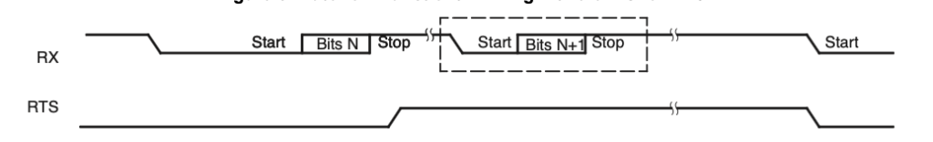
This seems to be a good choice and should work well as the peer ideally samples its CTS (=our RTS) line immediately before sending.
A quick internet search also revealed this issue with ARM’s AMBA PL011 from 2015 which matches our observation. It would be nice if this could get fixed on later versions of the RP2 MCU line (<= Hint for Raspberry Pi!).
In conclusion, the UART cannot be used for Bluetooth HCI with hardware flowcontrol without FIFO as it will loose bytes. With the FIFO enabled, the timing of RTS isn’t relevant as we can cache a few extra bytes in the FIFO without problems.
As we cannot use the hardware flowcontrol without the FIFO, we do the next obvious step and enable the FIFO. With the FIFO enabled, the thresholds for the UART interrupt flags changes from a single byte to a programmable threshold. This programmable threshold can be set to 1..7 and is multiplied by 4. The same caveat about TX Ready (UARTTXINTR) being transition-based instead of level-based still applies. However, as a positive surprise we also learn that the UART supports a “RX Timeout” which triggers the RX interrupt when at least one byte is in the FIFO and no further data has been received for 32-bit times. Without this, receiving data that are not a multiply of 4 would have become rather tricky.
Anyway, with the FIFO enabled, the IRQ-driven UART driver works as intended but we needlessly waste valuable CPU cycles by causing an interrupt per byte, which let’s us move on to a DMA-based implementation.
DMA Setup
Setting up DMA based on other examples was without surprises. The only noteworthy detail was that the RP2040 data sheet lists internal signals like UARTRXDMASREQ and UARTRXDMABREQ which indicate a difference between single character or burst character DMA requests, but neither of them can be enabled or referred to in the DMA setup or are mentioned in a UART or DMA register.
With our new hal_uart_dma_pico.c implementation the stack properly starts up. Yay!
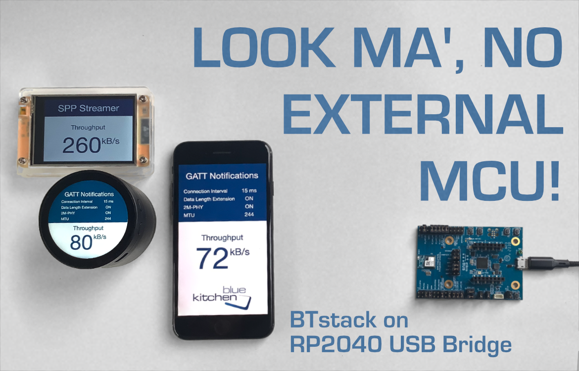
Demo Time
The easiest test is our gatt_streamer_server. It provides a LE Peripheral with a custom service which contains two characteristics. Once enabled, the demo sends data as fast as possible using the GATT Notification mechanism. With a iPhone 12 Mini, we are able to reach a throughput of 70 kB/s in this direction. This nicely shows that the optional Bluetooth features LE Data Length Extension and 2M-PHY are supported and actively used by both devices.
In addition to the iPhone, we run our LE Streamer Client on an ESP32-S3 and reached a throughput of up to 80 kB/s, which is only a bit more. This indicates that Apple has optimized their LE implementation in the last years – we speculate that they increased the number of LE-ACL packets exchanged per Connection Interval.
Finally, to also check Bluetooth Classic, we run our SPP Streamer Server on the Vela IF820 and connect with SPP Streamer Client running on a ESP32-2432S028R aka “Cheap Yellow Display”, which gets us between 250-260 kB/s.
While this is already quite nice, the Vela IF820 dev kit does not provide an audio codec and/or audio output. However, as we’re already using USB CDC for the console interface in BTstack, we could as well route audio over a USB Audio interface and learn something new. To be continued…