Existing ports
- BTstack Port for Ambiq Apollo2 with EM9304
- Archive of earlier ports
- BTstack Port for the Espressif ESP32 Platform
- BTstack Port for FreeBSD Systems
- BTstack Port for POSIX Systems with libusb Library
- BTstack Port for POSIX Systems with Intel Wireless 8260/8265 Controllers
- BTstack Port for Linux Systems
- BTstack Port for the Maxim MAX32630FTHR ARM Cortex-M4F
- BTstack Port for MSP432P401 Launchpad with CC256x
- BTstack Port with Cinnamon for Nordic nRF5 Series
- BTstack Port for POSIX Systems with H4 Bluetooth Controller
- BTstack Port for POSIX Systems with modern Infineon (CYW) H4 Bluetooth Controller
- BTstack Port for POSIX Systems with Atmel ATWILC3000 Controller
- BTstack Port for POSIX Systems with Dialog Semiconductor DA14531 Controller
- BTstack Port for POSIX Systems with Dialog Semiconductor DA14581 Controller
- BTstack Port for POSIX Systems with Dialog Semiconductor DA14585 Controller
- BTstack Port for POSIX Systems with NXP/Marvel H4 Bluetooth Controller
- BTstack Port for POSIX Systems with Zephyr-based Controller
- BTstack Port for QT with H4 Bluetooth Controller
- BTstack Port for QT with USB Bluetooth Dongle
- BTstack Port for Raspberry Pi with BCM4343 Bluetooth/Wifi Controller
- BTstack Port for Renesas Eval Kit EK-RA6M4 with DA14531
- BTstack Port for Renesas Target Board TB-S1JA with CC256x
- BTstack Port for Ezurio Vela IF820 Series
- BTstack Port for SAMV71 Ultra Xplained with ATWILC3000 SHIELD
- BTstack Port for STM32 F4 Discovery Board with CC256x
- BTstack Port for STM32 F4 Discovery Board with Ezurio Vela IF310 Devkit
- BTstack Port for STM32 F4 Discovery Board with USB Bluetooth Controller
- BTstack Port for STM32 Nucleo L073RZ Board with EM9304 Controller
- BTstack Port with Cinnamon for Semtech SX1280 Controller on Miromico FMLR-80
- BTstack Port with Cinnamon for Semtech SX1280 Controller on STM32L476 Nucleo
- BTstack Port for STM32WB55 Nucleo Boards using FreeRTOS
- BTstack on Web using WebSerial
- BTstack Port for WICED platform
- BTstack Port for Windows Systems with Bluetooth Controller connected via Serial Port
- BTstack Port for Windows Systems with DA14585 Controller connected via Serial Port
- BTstack Port for Windows Systems with Zephyr-based Controller
- BTstack Port for Windows Systems using the WinUSB Driver
- BTstack Port for Windows Systems with Intel Wireless 8260/8265 Controllers
- BTstack Port for Zephyr RTOS
BTstack Port for Ambiq Apollo2 with EM9304
This port uses the Ambiq Apollo2 EVB and the Ambiq EM9304 (AM BLE) shield. HAL and BSP from Ambiq Suite 1.2.11 were used together with the regular ARM GCC toolchain. Firmware upload is possible via the internal J-Link interface or the 10-pin Mini ARM-JTAG Interface.
Hardware
Ambiq Apollo2 EVB + AM_BLE Shield - http://ambiqmicro.com/apollo-ultra-low-power-mcus/apollo2-mcu/
Software
AmbiqSuite: - http://ambiqmicro.com/apollo-ultra-low-power-mcus/apollo2-mcu/
Please clone BTstack as AmbiqSuite/third-party/bstack folder into the AmbiqSuite.
Create Example Projects
To create example GCC projects, go to the Apollo2-EM9304 folder
$ cd port/apollo2-em9304
and run make
$ ./create_examples.py
All examples are placed in the boards/apollo2_evb_am_ble/examples folder with btstack_ prefix.
Compile & Run Example Project
Go to to the gcc folder of one of the example folders and run make
$ make
To upload, please follow the instructions in the Apollo Getting Started documents.
Debug output
printf is routed over the USB connector of the EVB at 115200.
In port/apollo2-em9304/btstack_config.h additional debug information can be enabled by uncommenting ENABLE_LOG_INFO.
Also, the full packet log can be enabled in src/btstack_port.c by uncommenting the hci_dump_init(..) line. The console output can then be converted into .pklg files for OS X PacketLogger or WireShark by running tool/create_packet_log.py
TODO
- BTstack's TLV persisten storage via Flash memory is not implemented yet.
- SPI Fullduplex: Newer Apollo 2 revisions supports SPI Full Duplex. The Ambiq Suite 1.2.11 does not cover Full Duplex with IRQ callback. It could be emulated by setting the Full Duplex mode and doing a regular write operation. When the write is complete, the received data can be read from the IOM FIFO.
- During MCU sleep without an ongoing SPI operation, the SPI could be fully disabled, which would reduce enrgey consumption.
Archive of earlier ports
The ports in this folder are not recommended for new designs. This does not mean that the target hardware is not suitable for new designs, just that the ports would need to reworked/refreshed.
List of ports with reason for move to this archive:
-
MSP430 ports: The ports used the not-maintained version of the community MSP430 gcc port, which does not support more than 64 kB of FLASH RAM. A current port should use the official GCC version sponsored by TI. In addition, the MSP430 UART does not support hardware RTS/CTS. For a new port, our ringbuffer approach should be used. Individual ports:
- EZ430-RF256x Bluetooth Evaluation Tool for MSP430
- MSP430F5438 Experimenter Board for MSP430 with Bluetooth CC2564 Module Evaluation Board
- MSP-EXP430F5529LP LaunchPad with Bluetooth CC2564 Module Evaluation Board and EM Adapter BoosterPack with additional 32768Hz quartz oscillator
-
Ports for Broadcom/Cypress Controllers using HCI Transport H5: The PatchRAM cannot be uploaded via H5. This requires to upload the PatchRAM using H4 mode and then to start the stack using H5 transport. In addition, several bugs have been observed in H5 mode, e.g. LE Encrypt not wokring. Unless absolutely neccessary, it's better to use H4 mode.
- Unix-based system connected to Broadcom/Cypress Bluetooth module via H5 over serial port
- Broadcom platforms that support the WICED SDK via H5 UART, see wiced-h4
-
Port for MicroChip PIC32 with Harmony Framework: the original port was for Harmony v1, while there's a Harmony V3 out since 2019:
-
iOS port:
- BTstack on iOS is not supported anymore.
-
raspi: it tries to directly access the built-in Bluetooth Controller which is wired differently with each version. Please use the Linux port instead which accesses the Controller via the official kernel drivers.
-
POSIX-H4-Airoc: use POSIX-H4 with flag
--airoc-download-modeinstead -
POSIX-H4-Zephyr: use POSIX-H4 with option `--baud 1000000' instead
BTstack Port for the Espressif ESP32 Platform
Setup
- Follow Espressif IoT Development Framework (ESP-IDF) setup to install XTensa toolchain and the ESP-IDF.
- Currently used for testing: ESP-IDF v5.4
Usage
Please note: Since BTstack v1.7, BTstack sources are not and should not be copied into ${ESP_IDF}/components folder.
Please remove ${ESP_IDF}/components/btstack
The current build system allows to build all provided examples for all supported ESP32 versions. By default, the 'gatt_counter' example will be build for the original ESP32.
To select example 'gatt_streamer_server' and the ESP32-C3:
EXAMPLE='gatt_streamer_server' idf.py set-target esp32c3
To get a list of valid targets:
idf.py set-target
To get a list of BTstack examples:
idf.py list-examples
To change the example:
idf.py fullclean
To compile the example, run:
idf.py build
To upload the binary to your device, run:
idf.py -p PATH-TO-DEVICE flash
To get debug output, run:
idf.py monitor
You can quit the monitor with CTRL-].
Configuration
The configuration file 'btstack_config.h' is provided by the main project via the btstack_config component in
components/btstack_config/btstack_config.h
By default, BTstack routes SCO over HCI. This can be changed via menu config entry:
Component config -> Bluetooth -> Controller Options -> BR/EDR Sync(SCO/eSCO) default data path.
Integration into custom projects
The esp32 port (this folder) contains the components 'btstack' and 'btstack_config'. It can be compiled out-of-tree by setting the environment variable BTSTACK_ROOT, example:
BTSTACK_ROOT=/path/to/btstack EXAMPLE='gatt_streamer_server' idf.py build
Limitations
Issues with the Bluetooth Controller Implementation
There are different issues in the Bluetooth Controller of the ESP32 that is provided in binary. We've submitted appropriate issues on the GitHub Issues page here: https://github.com/espressif/esp-idf/issues/created_by/mringwal
Audio playback
Audio playback is implemented by btstack_audio_esp32_v4.c resp. btstack_audio_esp32_v5.c and supports generic I2S codecs as well as the ES8388 on the
ESP32 LyraT v4.3 devkit.
Due to the various ESP32 variants, please double check the I2S Configuration in the mentioned audio file and verify that the correct menuconfig options are set.
For a generic ESP32, the first I2S interface is used with with the following pin out:
| ESP32 pin | I2S Pin |
|---|---|
| GPIO0 | MCK |
| GPIO5 | BCLK |
| GPIO25 | LRCK |
| GPIO26 | DOUT |
| GPIO35 | DIN |
If support for the LyraT v4.3 is enabled via menuconfig - Example Board Configuration --> ESP32 board --> ESP32-LyraT V4.3, CONFIG_ESP_LYRAT_V4_3_BOARD gets defined and the ES8388 will be configured as well.
We've also used the MAX98357A on the Adafruit breakout board.
The simplest audio example is the mod_player, which plays back an 8 kB sound file and the a2dp_sink_demo that implements a basic Bluetooth loudspeaker.
You can test the audio input with the audio_duplex example.
ESP32 printf/log
The BTstack port setups a buffered output for printf/ESP log macros. However, if that gets full, the main thread will get blocked. If you're playing audio, e.g. a2dp_sink_demo, and a lot of text is sent over the UART, this will cause audio glitches as the I2S DMA driver isn't re-filled on time. If this happens, you can increase the UART baudrate, reduce the debug output or increase the output buffer size - or any combination of these. :)
Multi-Threading
BTstack is not thread-safe, but you're using a multi-threading OS. Any function that is called from BTstack, e.g. packet handlers, can directly call into BTstack without issues. For other situations, you need to provide some general 'do BTstack tasks' function and trigger BTstack to execute it on its own thread.
To call a function from the BTstack thread, you can use btstack_run_loop_execute_on_main_thread allows to directly schedule a function callback, i.e. 'do BTstack tasks' function, from the BTstack thread. The called function then checks for pending BTstack tasks and executes them.
BTstack Port for FreeBSD Systems
Overview
This port assumes that FreeBSD provides an ng_hci netgraph node for a connected Bluetooth Controller. In most cases, these are Bluetooth USB dongles or built-in Bluetooth Controller connected via USB.
For Bluetooth Controllers connected via UART, the POSX-H4 port might be a better option als
Implementation details
In FreeBSD 13.2, the hci node is connected to a l2cap node and a btsock_hci_raw node. In order to take control, this port create a custom netgraph ng_socket node and connect to the 'acl' and 'raw' hooks of the hci node. The OS Bluetooth functionality will be interrupted.
Compilation
BTstack's FeeeBSD port does not have additional dependencies. To compile the cmake project with Make
mkdir build
cd build
cmake ..
make
or using Ninja:
mkdir build
cd build
cmake -G Ninja ..
ninja
Running the examples
As the port needs to reconfigure the Bluetooth netgraph node, it needs to run with root privileges. It tries to connect to 'ubt0hci' by default. If your Bluetooth Controller is different, you can select it with '-u node' On start, BTstack prints the path to the packet log and prints the information on the detected Buetooth Controller.
$ sudo gatt_counter
Packet Log: /tmp/hci_dump.pklg
BTstack counter 0001
BTstack up and running on 00:1A:7D:DA:71:13.
ToDO
- drop privileges after startup
- auto-detect ng_hci node
- support for profiles that require SCO: HFP & HSP
BTstack Port for POSIX Systems with libusb Library
Compilation
The quickest way to try BTstack is on a Linux or macOS system with an additional USB Bluetooth dongle. It requires pkg-config and libusb-1.0 or higher to be installed.
On a recent Debian-based system, all you need is:
sudo apt-get install gcc git cmake ninja-build pkg-config libusb-1.0 portaudio19-dev
When everything is ready, you compile all examples with make:
make
or using CMake + Ninja:
mkdir build
cd build
cmake -G Ninja ..
ninja
Environment Setup
Linux
On Linux, the USB Bluetooth dongle is usually not accessible to a regular user.
You can add a udev rule for your dongle to extend access rights to user processes.
For this, create /etc/udev/rules.d/btstack.rules and add this
# Match all devices from CSR
SUBSYSTEM=="usb", ATTRS{idVendor}=="0a12", MODE="0666"

# Match all devices from Realtek
SUBSYSTEM=="usb", ATTRS{idVendor}=="0bda", MODE="0666"

# Match Cypress Semiconductor / Broadcom BCM20702A, e.g. DeLOCK Bluetooth 4.0 dongle
SUBSYSTEM=="usb", ATTRS{idVendor}=="0a5c", ATTRS{idProduct}=="21e8", MODE="0666"

# Match Asus BT400
SUBSYSTEM=="usb", ATTRS{idVendor}=="0b05", ATTRS{idProduct}=="17cb", MODE="0666"

# Match Laird BT860 / Cypress Semiconductor CYW20704A2
SUBSYSTEM=="usb", ATTRS{idVendor}=="04b4", ATTRS{idProduct}=="f901", MODE="0666"
macOS
On macOS, the OS will try to use a plugged-in Bluetooth Controller if one is available. It's best to to tell the OS to always use the internal Bluetooth Contoller.
For this, execute:
sudo nvram bluetoothHostControllerSwitchBehavior=never
and then reboot to activate the change.
Note: if you get this error,
libusb: warning [darwin_open] USBDeviceOpen: another process has device opened for exclusive access
libusb: error [darwin_reset_device] ResetDevice: device not opened for exclusive access
and you didn't start another instance and you didn't assign the USB Controller to a virtual machine, macOS uses the plugged-in Bluetooth Controller. Please configure NVRAM as explained and try again after a reboot.
macOS 26 Tahoe
From macOS 26.0 until now (currently macOS 26.4) access to a Bluetooth Controller via libusb causes a kernel panic.
The libusb project has a closed issue about it here: https://github.com/libusb/libusb/issues/1762 They closed it as the crash happens in the kernel and they or we cannot fix this. Please send bug/crash reports via the Feedback Assistant to Apple.
To use BTstack on macOS 26, you're best option is to run a Linux distribution like Debian or Ubuntu in a virtual machine and acess the USB Bluetooth Dongle from there. We can confirm that BTstack works as expected in a Ubuntu 2024 VM with UTM and the CSR8510 USB dongle.
Broadcom/Cypress/Infineon Controllers
During startup BTstack queries the Controlle for the Local Name, which is set to the Controller type (e.g. 'BCM20702A). The chipset support uses this information to look for a local PatchRAM file of that name and uploads it.
Realtek Controllers
During startup, the libusb HCI transport implementations reports the USB Vendor/Product ID, which is then forwarded to the Realtek chipset support. The chipset support contains a mapping between USB Product ID and ( Patch, Configuration ) files. If found, these are uploaded.
Running the examples
BTstack's HCI USB transport will try to find a suitable Bluetooth module and use it.
On start, BTstack will try to find a suitable Bluetooth module. It will also print the path to the packet log as well as the USB path.
$ ./le_counter
Packet Log: /tmp/hci_dump.pklg
BTstack counter 0001
Packet Log: /tmp/hci_dump_6.pklg
USB device 0x0a12/0x0001, path: 06
Local version information:
- HCI Version    0x0006
- HCI Revision   0x22bb
- LMP Version    0x0006
- LMP Subversion 0x22bb
- Manufacturer 0x000a
BTstack up and running on 00:1A:7D:DA:71:01.
If you want to run multiple examples at the same time, it helps to fix the path to the used Bluetooth module by passing -u usb-path to the executable.
Example running le_streamer and le_streamer_client in two processes, using CSR Bluetooth dongles at USB path 6 and 4:
./le_streamer -u 6
Specified USB Path: 06
Packet Log: /tmp/hci_dump_6.pklg
USB device 0x0a12/0x0001, path: 06
Local version information:
- HCI Version    0x0006
- HCI Revision   0x22bb
- LMP Version    0x0006
- LMP Subversion 0x22bb
- Manufacturer 0x000a
BTstack up and running on 00:1A:7D:DA:71:01.
To start the streaming, please run the le_streamer_client example on other device, or use some GATT Explorer, e.g. LightBlue, BLExplr.

$ ./le_streamer_client -u 4
Specified USB Path: 04
Packet Log: /tmp/hci_dump_4.pklg
USB device 0x0a12/0x0001, path: 04
Local version information:
- HCI Version    0x0006
- HCI Revision   0x22bb
- LMP Version    0x0006
- LMP Subversion 0x22bb
- Manufacturer 0x000a
BTstack up and running on 00:1A:7D:DA:71:02.
Start scanning!
BTstack Port for POSIX Systems with Intel Wireless 8260/8265 Controllers
Same as port/libusb, but customized for Intel Wireless 8260 and 8265 Controllers. These controller require firmware upload and configuration to work. Firmware and config is downloaded from the Linux firmware repository.
Compilation
Requirements: - pkg-config - libusb-1.0
On a recent Debian-based system, all you need is:
apt-get install gcc git libusb-1.0 pkg-config
When everything is ready, you compile all examples with:
make
Environment
On Linux, the USB Bluetooth dongle is usually not accessible to a regular user. You can either: - run the examples as root - add a udev rule for your dongle to extend access rights to user processes
To add an udev rule, please create /etc/udev/rules.d/btstack.rules and add this
# Match all devices from CSR
SUBSYSTEM=="usb", ATTRS{idVendor}=="0a12", MODE="0666"

# Match DeLOCK Bluetooth 4.0 dongle
SUBSYSTEM=="usb", ATTRS{idVendor}=="0a5c", ATTRS{device}=="21e8", MODE="0666"

# Match Asus BT400
SUBSYSTEM=="usb", ATTRS{idVendor}=="0b05", ATTRS{device}=="17cb", MODE="0666"

# Match Laird BT860 / Cypress Semiconductor CYW20704A2
SUBSYSTEM=="usb", ATTRS{idVendor}=="04b4", ATTRS{device}=="f901", MODE="0666"

# Match Intel Wireless 8260 8265
SUBSYSTEM=="usb", ATTRS{idVendor}=="8027", ATTRS{device}=="0a2b, MODE="0666"
On macOS, the OS will try to use a plugged-in Bluetooth Controller if one is available. It's best to to tell the OS to always use the internal Bluetooth Contoller.
For this, execute:
sudo nvram bluetoothHostControllerSwitchBehavior=never
and then reboot to activate the change.
Running the examples
BTstack's HCI USB transport will try to find a suitable Bluetooth module and use it.
On start, BTstack will try to find a suitable Bluetooth module. It will also print the path to the packet log as well as the USB path.
$ ./le_counter
Packet Log: /tmp/hci_dump.pklg
USB Path: 03-01-04-03
Firwmare ./ibt-12-16.sfi
Firmware upload complete
Firmware operational
Done 1
BTstack counter 0001
USB Path: 03-01-04-03
BTstack up and running on F8:34:41:D5:BE:6F.
If you want to run multiple examples at the same time, it helps to fix the path to the used Bluetooth module by passing -u usb-path to the executable.
Example running le_streamer and le_streamer_client in two processes, using Bluetooth dongles at USB path 6 and 4:
./le_streamer -u 6
Specified USB Path: 06
Packet Log: /tmp/hci_dump_6.pklg
USB Path: 06
BTstack up and running on 00:1A:7D:DA:71:13.
To start the streaming, please run the le_streamer_client example on other device, or use some GATT Explorer, e.g. LightBlue, BLExplr.

$ ./le_streamer_client -u 4
Specified USB Path: 04
Packet Log: /tmp/hci_dump_4.pklg
USB Path: 04
BTstack up and running on 00:1A:7D:DA:71:13.
Start scanning!
BTstack Port for Linux Systems
While BTstack can directly work on Linux with most Bluetooth Controllers that are connected via UART (port/posix-h4) or USB (port/libusb), it might be convenient to use the Linux Bluetooth Subsystem in some cases, e.g. if the Bluetooth Controller uses other transports (such as SDIO) or the Controller is already fully configured by the distributions.
Compilation
In addition to regular C build tools, you also need the Bluetooth development package installed.
sudo apt install libbluetooth-dev
Now you can compile it as usual with CMake
mkdir build
cd build
cmake ..
make
Running the examples
Please make sure that BlueZ is not installed or at least disabled
sudo systemctl stop bluetooth
sudo systemctl disable bluetooth
sudo systemctl mask bluetooth
Also make sure that the chosen device (here, hci0) is down
sudo hciconfig hci0 down
To check
hciconfig hci0

hci0:   Type: Primary  Bus: USB
        BD Address: 00:1A:7D:DA:71:13  ACL MTU: 1021:8  SCO MTU: 64:1
        DOWN
        RX bytes:566359 acl:0 sco:0 events:40 errors:0
        TX bytes:2174059 acl:2694 sco:0 commands:329 errors:0
To access the Bluetooth Controller, you can either run the examples as root, or, set the necessary permissions for a compiled example, e.g.
sudo setcap 'cap_net_raw,cap_net_admin+eip' gatt_counter
Now, you can run this example as a regular user
$ ./gatt_counter
Packet Log: /tmp/hci_dump.pklg
BTstack counter 0001
BTstack up and running on 00:1A:7D:DA:71:13.
Status
When running gatt_counter, a basic LE Peripheral with a GATT Service, the first two connections fail, while the third and later work as expected. There's no difference when looking at the HCI Trace with btmon, just that no ACL packets are received in the failing attempts.
BTstack Port for the Maxim MAX32630FTHR ARM Cortex-M4F
This port uses the MAX32630FTHR ARM Cortex M4F Board with the onboard TI CC2564B Bluetooth controller. It usually comes with the DAPLINK Programming Adapter. The DAPLINK allows to upload firmware via a virtual mass storage device (like mbed), provides a virtual COM port for a console, and enables debugging via the SWD interface via OpenOCD.
The port uses non-blocking polling UART communication with hardware flow control for Bluetooth controller. It was tested and achieved up to 1.8 Mbps bandwidth between two Max32630FTHR boards.
Prerequisites
Maxim SDK
The Maxim has dropped the support for MAX32630 and is not recommended for new designs and it is also dropped from the latest SDK.
Maxim SDK Mirror
The required minimum set of files from the SDK are included in the port files port/max32630-fthr/maxim for convenience and to support linux build.
(For reference) ARM Cortex Toolchain - a.k.a. the old Maxim SDK
The ARM Cortex Toolchain is free software that provides peripheral libraries, linker files, initial code and some board files. It also provides Eclipse Neon and Maxim modified OpenOCD to program the microcontroller together with various examples for Maxim Cortex M4F ARM processors.
For debugging, OpenOCD can be used. The regular OpenOCD does not support Maxim ARM microcontrollers yet, but a modified OpenOCD for use with Maxim devices can be found in the Maxim ARM Toolchain.
Toolchain and Eclipse guide can be found in README.pdf file where the Maxim Toolchain is installed. Please note that this port was done using Makefiles.
ARM Toolchain Setup
Download and extract arm toolchain. Record extract folder as TOOLCHAIN_PATH.
Windows msys: arm-gnu-toolchain-14.2.rel1-mingw-w64-x86_64-arm-none-eabi.zip
WSL Linux: arm-gnu-toolchain-14.2.rel1-x86_64-arm-none-eabi.tar.xz
Python - 3.12 or newer
Download and install python and make sure the alias python is accessible in the build terminal.
MSYS2 setup - (windows only)
The ARM Cortex Toolchain contains msys1.0, but it is complete (lacking unzip) and it is recommended that to use a more recent msys2.
Download and install msys2 - https://github.com/msys2/msys2-installer/releases/
- Install with option to Run msys2 after completion.
- Record install folder as MSYS_PATH
- Install required packages make and unzip.
pacman -S make unzip
- close msys2
Environment Variables
The BTSTACK_ROOT, MAXIM_PATH, and PATH must point to the previously setup tools as absolute paths.
The BTSTACK_ROOT is provided as relative path for examples in port/max32630-fthr/example/project/Makefile, but must be provided otherwise.
If not provided the MAXIM_PATH is set based on BTSTACK_ROOT.
Windows msys:
Run scripts/setenv.bat or set manually
<a name="sec:max32630-fthrPort"></a>

## TOOLCHAIN_PATH=%EXTRACT_PATH%
<a name="sec:max32630-fthrPort"></a>

## MSYS_BIN=%MSYS_PATH%\usr\bin
set PATH=%TOOLCHAIN_PATH%/bin;%MSYS_BIN%;%PATH%
WSL Linux:
PATH="${TOOLCHAIN_PATH}/bin:${PATH}"
Build
The examples can be compiled using make. The build is implemented as a combination of several make and python scripts. For details see the scripts port/max32630-fthr, port/max323630-fthr/scripts, and port/max32630-fthr/example/template folders.
Running the make script port/max32630-fthr/Makefile will create Makefiles for the projects. And the projects are built running make scripts port/max32630-fthr/example/Makefile or port/max32630-fthr/example/project/Makefile.
cd %BTSTACK_ROOT%/port/max32630-fthr
.../port/max32630-fthr$ make
> Creating example projects:
> project - a2dp_sink_demo
> project - a2dp_source_demo
> project - ancs_client_demo
> ...
.../port/max32630-fthr$ cd example
<a name="sec:max32630-fthrPort"></a>

## build a make target default(all), dual, general, classic, or ble
.../port/max32630-fthr/example$ make
<a name="sec:max32630-fthrPort"></a>

## or build individual project e.g. gatt_counter
.../port/max32630-fthr/example$ cd gatt_counter
.../port/max32630-fthr/example/gatt_counter$ make
In each example/project folder the make target is to build .elf file in the build folder which is convenient for debugging using Eclipse or GDB.
For flashing via the virtual USB drive, the make also builds .bin file relative to the project ../bin/project.bin e.g. which is for the examples example/bin.
Flashing Max32630 ARM Processor
A firmware binary can be flashed either by copying the .bin file to the DAPLINK mass storage drive, or by using OpenOCD on the command line, or from Eclipse CDT.
The simplest way is drag and drop the generated .bin file to the DAPLINK mass storage drive. Once the file is copied to the mass storage device, the DAPLINK should program and then run the new firmware.
Alternatively, OpenOCD can be used to flash and debug the device. A suitable programming script can be found in the scripts folder.
Debugging
OpenOCD can also be used for developing and especially for debugging. Eclipse or GDB via OpenOCD could be used for step by step debugging.
Debug output
printf messages are redirected to UART2. UART2 is accessible via the DAPLINK Programming Adapter as a virtual COM port at 115200 baud with no flow control. If this doesn't work for you, you can connect P3_1 (UART TX) of the MAX32630FTHR board to a USB-to-UART adapter.
Additional debug information can be enabled by uncommenting ENABLE_LOG_INFO in the src/btstack_config.h header file and a clean rebuild.
TODOs
- Support for BTSTACK_STDIN
- Add flash-openocd to Makefile template
- Add Eclipse CDT projects for max32630fthr
- Implement hal_led.h to control LED on board
BTstack Port for MSP432P401 Launchpad with CC256x
This port is for the the TI MSP432P401R Launchpad with TI's CC256x Bluetooth Controller using TI's DriverLib (without RTOS). For easy development, Ozone project files are generated as well.
As the MSP432P401 does not have support for hardware RTS/CTS, this port makes use of Ping Pong DMA transfer mode (similar to circular DMA on other MCUs) to use two adjacent receive buffers and raise RTS until a completed buffer is processed.
Hardware
As Bluetooth Controller, there are two BoosterPacks that can be use: 1. BOOST-CC2564MODA CC2564B BoosterPack (USD 20) 2. Evaluation Module (EM) Adapto (USD 20) with one of the CC256x modules: - CC2564B Dual-mode Bluetooth® Controller Evaluation Module (USD 20) - CC2564C Dual-mode Bluetooth® Controller Evaluation Module (USD 60)
The CC2564B Booster pack is around USD 20 while thhe EM Adapter with the CC2564C module is around USD 80.
The project in the BTstack repo `port/msp432p401lp-cc256x' is configured for the EM Adapter + newer CC2564C module.
When using the CC2564B (either as BOOST-CC2564MODA or CC2564B Dual-mode Bluetooth® Controller Evaluation Module), the bluetooth_init_cc2564B_1.8_BT_Spec_4.1.c must be used as cc256x_init_script. See Makefile variable INIT_SCRIPT.
When using the CC2564B Booster Pack, please use uncomment the defines for the GPIO definition (search for BOOST-CC2564MODA)
When using the EM Adapter Booster Pack, please make sure to solder a 32.768 kHz quarz oscillator as explained in 4.7 of the EM Wireless Booster Pack User Guide. If you don't have an oscillator of that size, you might solder one upside done (turtle-on-back style) to the unused upper right pad and wire GCC, VCC, and clock with thin wires.
Software
To build all examples, you need the regular ARM GCC toolcahin installed. Run make
$ make
All examples and the .jdebug Ozone project files are placed in the 'gcc' folder.
Flash And Run The Examples
The Makefile builds different versions: - example.elf: .elf file with all debug information - example.bin: .bin file that can be used for flashing
There are different options to flash and debug the MSP432P401R LaunchPad. If all but the jumpers for power (the left three) are removed on J101, an external JTAG like SEGGER's J-Link can be connected via J8 'MSP432 IN'.
Run Example Project using Ozone
When using an external J-Link programmer, you can flash and debug using the cross-platform SEGGER Ozone Debugger. It is included in some J-Link programmers or can be used for free for evaluation usage.
Just start Ozone and open the .jdebug file in the build folder. When compiled with ENABLE_SEGGER_RTT, the debug output shows up in the Terminal window of Ozone.
Debug output
All debug output is send via SEGGER RTT or via USART2. To get the console from USART2, remove ENABLE_SEGGER_RTT from btstack_config.h and open a terminal to the virtual serial port of the Launchpad at 115200.
In btstack_config.h resp. in example/btstack_config.h of the generated projects, additional debug information can be disabled/enabled via ENABLE_LOG_INFO.
Also, the full packet log can be enabled in main.c by uncommenting the hci_dump_init(..) line. The output can then be converted into .pklg files for OS X PacketLogger or WireShark by running tool/create_packet_log.py
GATT Database
In BTstack, the GATT Database is defined via the .gatt file in the example folder. The Makefile contains rules to update the .h file when the .gatt was modified.
BTstack Port with Cinnamon for Nordic nRF5 Series
Cinnamon is BlueKitchen's minimal, yet robust Controller/Link Layer implementation for use with BTstack.
In contrast to common Link Layer implementations, our focus is on a robust and compact implementation for production use, where code size matters (e.g. current code size about 8 kB).
Status
The current implementation supports a single Peripheral role, or, passive scanning in Observer role. In the Peripheral role, channel map updates, as well as connection param updates are supported.
Support for LE Central Role as well as Encryption is planned but not supported yet.
Requirements
- arm-none-eabi toolchain
- Nordic's nRF5-SDK
Supported Hardware
All nNRF5x SOCs. Built files are provided for PCA10040 (52832 DK), but others can be supported with minimal changes.
Use
- Provide path to nRF5-SDK either in
NRF5_SDK_ROOTenvironment variable or directly inpca10040/armgcc/Makefile. - run make
- All supported examples are built in the
buildfolder. - You can use Segger's OZONE with the provided
EXAMPLE.jdebugproject file to flash and run the examples.
BTstack Port for POSIX Systems with H4 Bluetooth Controller
Configuration
Most Bluetooth Bluetooth Controllers connected via UART/H4 require some special configuration, e.g. to set the UART baud rate, and/or require firmware patches during startup. In this port, we've tried to do most of these automatically based on information gathered from the Bluetooth Controller. Here's some Controller specific details:
TI CC256x
The CC2564x needs the correct init script to start up. The Makfile already has entries for most silicon revisions:
- CC2560: bluetooth_init_cc2564_2.14.c
- CC2564B: bluetooth_init_cc2564B_1.8_BT_Spec_4.1.c
- CC2564C: bluetooth_init_cc2564C_1.5.c
Please pick the correct one. The main.c verifies that the correct script is loaded, but the init script is linked to the executable.
Broadcom/Cypress/Infineon Controllers
The correct firmware file needs to be provided in the current working directory. The Makefile / CMake build downloads the one for the BCM43430 e.g. found on later Raspberry Pi editions.
Nordic Controller with HCI UART firmware
We maintain an enhanced / configured version of the official HCI UART example here: https://github.com/bluekitchen/hci_uart_iso_timesync/tree/main
The main difference of Zephyr-based Nordic Bluetooth Controllers is that: - the nRF52- and nRF54-Series use 1000000 as baud rate instead of 115200 - they don't have a public BD_ADDR.
You can use these by setting the baudrate to 1000000, e.g. like this
$ ./gatt_counter -u /dev/tty.usbmodem1234 --baud 1000000
The fixed random static address used automatically.
Build with Make
BTstack's POSIX-H4 does not have additional dependencies. You can directly run make
$ make
Build with CMake on the command line
To configure and build all examples with CMake/Ninja from the repository root, use:
$ cmake -S port/posix-h4 -B build/posix-h4 -G Ninja
$ cmake --build build/posix-h4
To build a single example only, specify the target explicitly, for example:
$ cmake --build build/posix-h4 --target gatt_counter
Build with CMake in Visual Studio Code
The repository contains a shared VS Code workspace file for this port:
port/posix-h4/btstack-posix-h4.code-workspace
Open this workspace file in Visual Studio Code using File->Open Workspace from File.
It shows the full BTstack repository in the file explorer, but configures CMake to use port/posix-h4/CMakeLists.txt.
Setup
- Install the
CMake Toolsextension - Open
port/posix-h4/btstack-posix-h4.code-workspace
Build an example
- Open the Command Palette
- Run
CMake: Configure - Run
CMake: Select Build Target - Pick an example, e.g.
gatt_counter - Run
CMake: Build
The executable will be created in:
port/posix-h4/build
Run an example
Open a terminal in Visual Studio Code and start the example from the build directory, for example:
$ cd port/posix-h4/build
$ ./gatt_counter
Running from the build directory is useful as controller-specific firmware and init files downloaded by the CMake build are placed there as well.
Command-line options
All examples provide the following command line options:
--help               | -h                       print (this) help.
--logfile            | -l  LOGFILE              set file to store debug output and HCI trace.
--logformat          | -f  btsnoop|bluez|pklg   set file format to store debug output in.
--reset-tlv          | -r                       reset bonding information stored in TLV.
--tty                | -u  TTY                  set path to Bluetooth Controller.
--bd-addr            | -m  BD_ADDR              set random static Bluetooth address.
--baudrate           | -b  BAUDRATE             set initial baudrate.
--airoc-download-mode| -d                       enable AIROC Download Mode for newer CYW55xx Controller
Infineon AIROC Controller
Newer Infineon Airoc (tm) Controllers like the CYW55xx series accept PatchRAM upload only in a so-called 'Download Mode' or 'Auto-Baud Mode' which is entered by asserting CTS (low) and starting/resetting the controller via BT_REG_EN. The PatchRAM name is retrieved via a custom HCI Command from the Controller and loaded from the current folder.
To enable this mode, please provide '--airoc-download-mode' on the command line.
As this doing a power cycle is usually not possible on a desktop system, this port request the user to press the "RESET" button while showing a countdown.
Running the examples
On start, BTstack prints the path to the packet log and prints the information on the detected Buetooth Controller.
$ ./le_counter
Packet Log: /tmp/hci_dump.pklg
BTstack counter 0001
BTstack up and running on 00:1A:7D:DA:71:13.
Please note that BTstack will increase the baudrate. Before starting again, you should reset or power-cycle the Bluetooth Controller.
BTstack Port for POSIX Systems with modern Infineon (CYW) H4 Bluetooth Controller
This port has been archive as port/archive/posix-h4-airoc.
You can use modern Infineon AIROC Controllers that require download mode with the regular posix-h4 port by
passing --airoc-download-mode, e.g. like this
$ ./gatt_counter -u /dev/tty.usbserial-1234 --airoc-download-mode
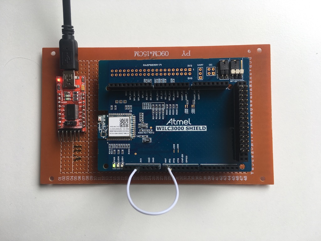
BTstack Port for POSIX Systems with Atmel ATWILC3000 Controller
This port allows to use the ATWILC3000 connected via UART with BTstack running on a POSIX host system, see test setup below (which lacks a proper RESET button).
Compilation
$ make
The Makefile downloads the wilc3000_bt_firmware.bin firmware from the GitHub atwilc3000/firmware repo.
Usage
Just run any of the provided examples, e.g.
$ ./le_counter
At start, the firmware file is first uploaded to the ATWILC3000, before BTstack start up.
Please note that it configures the ATWILC3000 for a higher baud rate it does not detect if the firmware has already been downloaded, so you need to reset the ATWILC3000 before starting an example.
Tested with the official ATWILC3000 SHIELD on OS X.
BTstack Port for POSIX Systems with Dialog Semiconductor DA14531 Controller
This port allows to use the DA14531 connected via UART with BTstack running on a POSIX host system.
Instead of storing the HCI firmware in the OTP, it first downloads the hci_531_active_uart_460800.hex firmware from the 6.0.16.1144 SDK, before BTstack starts up.
After Power Cycle, please start one of the test applications and press the Reset button to trigger firmware download.
Please note that it does not detect if the firmware has already been downloaded, so you need to Power Cycle the DA14531 before starting an example again.
Alternatively, after running one of the examples once to upload the firmware, you can use the regular 'posix-h4' port and change the initial UART baud rate to 460800 as long as you don't power cycle the dev kit.
For production use, the DA14531 could be power cycled from the main CPU during startup, e.g. after the call to btstack_chipset_da145xx_download_firmware_with_uart, or, the HCI firmware could be burned into the OTP.
Software Setup / Firmware
On the DA14531 USB Development Kit,
the UART is configured via DIP switched. By this, the mapping to the DA14531 GPIOs is fixed. In SDK 6.0.6.1144, the
GPIO mapping of RTS and CTS is flipped. In order to be able to us the same HCI firmware on both dev kits, we've
used the following configuration in user_perip_setup.h
    #define UART1_TX_PORT           GPIO_PORT_0
    #define UART1_TX_PIN            GPIO_PIN_0

    #define UART1_RX_PORT           GPIO_PORT_0
    #define UART1_RX_PIN            GPIO_PIN_1

    #define UART1_RTSN_PORT         GPIO_PORT_0
    #define UART1_RTSN_PIN          GPIO_PIN_4

    #define UART1_CTSN_PORT         GPIO_PORT_0
    #define UART1_CTSN_PIN          GPIO_PIN_3
We also increased the UART baudrate to 460800
#define UART1_BAUDRATE UART_BAUDRATE_460800
We also disabled the SLEEP mode in user_config.h:
static const sleep_state_t app_default_sleep_mode = ARCH_SLEEP_OFF;
After compilation with Keil uVision 5, the generated .hex file is copied into btstack/chipset/da145xx as
hci_531_active_uart_460800.hex, and then
`convert_hex_files" is used to convert it into a C data array.
Hardware Setup - Dev Kit Pro
To use the DA14531 Dev Kit Pro with BTstack, please make the following modifications: - Follow Chapter 4.1 and Figure 4 in the DA14531 Development Kit Pro Hardware User Manual UM-B-114 and set SW1 of the 14531 daughter board into position "BUCK" position marked with an "H" on the left side. - configure the dev kit for Full UART (4-wire) Configuration by adding jumper wires between J1 and J2
Hardware Setup - Dev Kit USB
To use the Dev Kit USB with BTstack, please make the following modifications: - Follow Chapter 5.6 in the DA14531 USB Development Kit Hardware UM-B-125 and set the DIP switches as described.
# Example Run
$ ./gatt_counter
Packet Log: /tmp/hci_dump.pklg
Phase 1: Download firmware
Phase 2: Main app
BTstack counter 0001
BTstack up and running on 80:EA:CA:70:00:08.
BTstack Port for POSIX Systems with Dialog Semiconductor DA14581 Controller
This port allows to use the DA14581 connected via UART with BTstack running on a POSIX host system.
It first downloads the hci_581_active_uart.hex firmware from the DA14581_HCI_3.110.2.12 SDK packet, before BTstack starts up.
Please note that it does not detect if the firmware has already been downloaded, so you need to reset the DA14581 before starting an example.
For production use, the HCI firmware could be flashed into the OTP and the firmware download could be skipped.
Tested with the official DA14581 Dev Kit on OS X.
BTstack Port for POSIX Systems with Dialog Semiconductor DA14585 Controller
This port allows to use the DA14585 connected via UART with BTstack running on a POSIX host system.
It first downloads the hci_581.hex firmware from the 6.0.8.509 SDK, before BTstack starts up.
Please note that it does not detect if the firmware has already been downloaded, so you need to reset the DA14585 before starting an example.
For production use, the HCI firmware could be flashed into the OTP and the firmware download could be skipped.
Tested with the official DA14585 Dev Kit Basic on OS X.
BTstack Port for POSIX Systems with NXP/Marvel H4 Bluetooth Controller
Configuration
Most Bluetooth Bluetooth Controllers connected via UART/H4 require some special configuration, e.g. to set the UART baud rate, and/or require firmware patches during startup. In this port, we've show how a NXP/Marvell Controller can be configured for use with BTstack. It's unclear if the required firmware file for older Controllers, e.g. 88W8997, can be detected during the firmware upload. This port selects the firmware for NXP 88W8997. For newer Controllers, e.g. IW416 or IW612, the firmware can be selected automatically.
Compilation
BTstack's posix-h4-nxp port does not have additional dependencies. You can directly run cmake and then your default build system. E.g. with Ninja:
mkdir build
cd build
cmake -G Ninja ..
ninja
Running the examples
Please reset the Controller first. On start, BTstack prints the path to the packet log.
$ ./gatt_counter
Packet Log: /tmp/hci_dump.pklg
BTstack counter 0001
BTstack up and running on 00:1A:7D:DA:71:13.
Issues
- NXP 88W8997 does not support SCO Flow Control which causes glitches when sending audio
ToDo
- increase baud rate for firmware upload
- skip firmware upload if firmware already present
- increase baud rate for application
BTstack Port for POSIX Systems with Zephyr-based Controller
The main difference of Zephyr-based Nordic Bluetooth Controllers is that: - the nRF52- and nRF54-Series use 1000000 as baud rate instead of 115200 - they don't have a public BD_ADDR.
You can use these with the regular posix-h4 port by setting the baudrate to 1000000, e.g. like this
$ ./gatt_counter -u /dev/tty.usbmodem1234 --baud 1000000
The fixed random static address used automatically.
BTstack Port for QT with H4 Bluetooth Controller
Windows is supported with the MinGW Kit.
Windows with MSVC or Embedded (bare metal) platforms not supported yet.
Configuration
Most Bluetooth Bluetooth Controllers connected via UART/H4 require some special configuration, e.g. to set the UART baud rate, and/or require firmware patches during startup. In this port, we've tried to do most of these automatically based on information gathered from the Bluetooth Controller. Here's some Controller specific details:
TI CC256x
The CC2564x needs the correct init script to start up. The Makfile already has entries for most silicon revisions:
- CC2560: bluetooth_init_cc2564_2.14.c
- CC2564B: bluetooth_init_cc2564B_1.8_BT_Spec_4.1.c
- CC2564C: bluetooth_init_cc2564C_1.5.c
Please pick the correct one. The main.c verifies that the correct script is loaded, but the init script is linked to the executable.
Broadcom BCM/CYW 43430
The correct firmware file needs to be provided in the current working directory. The Makefile downloads the one for the BCM43430 e.g. found on later Raspberry Pi editions. Please see the separate port/raspi, too.
Compilation
On all platforms, you'll need Qt Python 3 installed. On macOS/Linux libusb-1.0 or higher is required, too.
When everything is ready, you can open the provided CMakelists.txt project in Qt Creator and run any of the provided examples. See Qt documentation on how to compile on the command line or with other IDEs
You can also compile the project in a shell if you provide the path to the cmake folder of your Qt installation, e.g. on macOS with brew providing QT 5.15.16
cmake -DCMAKE_PREFIX_PATH=/opt/homebrew/Cellar/qt@5/5.15.16/lib/cmake/Qt5 ..
Running the examples
BTstack's HCI USB transport will try to find a suitable Bluetooth module and use it.
On start, BTstack will try to find a suitable Bluetooth module. It will also print the path to the packet log as well as the USB path.
$ ./gattcounter
Packet Log: /tmp/hci_dump.pklg
BTstack counter 0001
USB Path: 06
BTstack up and running on 00:1A:7D:DA:71:13.
BTstack Port for QT with USB Bluetooth Dongle
Uses libusb Library on macOS and Linux and WinUSB on Windows. Windows is supported with the MinGW Kit.
Windows with MSVC or Embedded (bare metal) platforms not supported yet.
Compilation
On all platforms, you'll need Qt Python 3 installed. On macOS/Linux libusb-1.0 or higher is required, too.
When everything is ready, you can open the provided CMakelists.txt project in Qt Creator and run any of the provided examples. See Qt documentation on how to compile on the command line or with other IDEs
You can also compile the project in a shell if you provide the path to the cmake folder of your Qt installation, e.g. on macOS with brew providing QT 5.15.16
cmake -DCMAKE_PREFIX_PATH=/opt/homebrew/Cellar/qt@5/5.15.16/lib/cmake/Qt5 ..
Environment Setup
Windows
To allow WinUSB to access an USB Bluetooth dongle, you need to install a special device driver to make it accessible to user space processes.
It works like this:
- Download Zadig
- Start Zadig
- Select Options -> “List all devices”
- Select USB Bluetooth dongle in the big pull down list
- Select WinUSB in the right pull down list
- Select “Replace Driver”
Linux
On Linux, the USB Bluetooth dongle is usually not accessible to a regular user. You can either: - run the examples as root - add a udev rule for your dongle to extend access rights to user processes
To add an udev rule, please create /etc/udev/rules.d/btstack.rules and add this
# Match all devices from CSR
SUBSYSTEM=="usb", ATTRS{idVendor}=="0a12", MODE="0666"

# Match DeLOCK Bluetooth 4.0 dongle
SUBSYSTEM=="usb", ATTRS{idVendor}=="0a5c", ATTRS{device}=="21e8", MODE="0666"

# Match Asus BT400
SUBSYSTEM=="usb", ATTRS{idVendor}=="0b05", ATTRS{device}=="17cb", MODE="0666"

# Match Laird BT860 / Cypress Semiconductor CYW20704A2
SUBSYSTEM=="usb", ATTRS{idVendor}=="04b4", ATTRS{device}=="f901", MODE="0666"
macOS
On macOS, the OS will try to use a plugged-in Bluetooth Controller if one is available. It's best to to tell the OS to always use the internal Bluetooth Contoller.
For this, execute:
sudo nvram bluetoothHostControllerSwitchBehavior=never
and then reboot to activate the change.
Note: if you get this error,
libusb: warning [darwin_open] USBDeviceOpen: another process has device opened for exclusive access
libusb: error [darwin_reset_device] ResetDevice: device not opened for exclusive access
and you didn't start another instance and you didn't assign the USB Controller to a virtual machine, macOS uses the plugged-in Bluetooth Controller. Please configure NVRAM as explained and try again after a reboot.
Running the examples
BTstack's HCI USB transport will try to find a suitable Bluetooth module and use it.
On start, BTstack will try to find a suitable Bluetooth module. It will also print the path to the packet log as well as the USB path.
$ ./gatt_counter
Packet Log: /tmp/hci_dump.pklg
BTstack counter 0001
USB Path: 06
BTstack up and running on 00:1A:7D:DA:71:13.
If you want to run multiple examples at the same time, it helps to fix the path to the used Bluetooth module by passing -u usb-path to the executable.
Example running le_streamer and le_streamer_client in two processes, using Bluetooth dongles at USB path 6 and 4:
./gatt_streamer_server -u 6
Specified USB Path: 06
Packet Log: /tmp/hci_dump_6.pklg
USB Path: 06
BTstack up and running on 00:1A:7D:DA:71:13.
To start the streaming, please run the le_streamer_client example on other device, or use some GATT Explorer, e.g. LightBlue, BLExplr.

$ ./le_streamer_client -u 4
Specified USB Path: 04
Packet Log: /tmp/hci_dump_4.pklg
USB Path: 04
BTstack up and running on 00:1A:7D:DA:71:13.
Start scanning!
BTstack Port for Raspberry Pi with BCM4343 Bluetooth/Wifi Controller
This port has been moved to port/archive/raspi.
For Raspberry Pi systems, use the port/linux port instead.
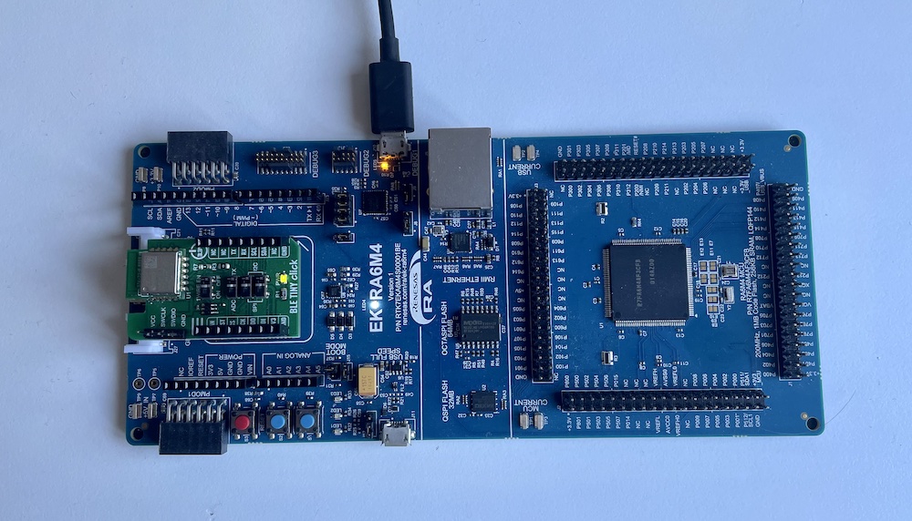
BTstack Port for Renesas Eval Kit EK-RA6M4 with DA14531
This port uses the Renesas EK-RA6M4 and a Renesas DA14531 Controller on the MikroeE BLE Tiny Click board
Renesas e2 Studio (Eclise-based) was used with the FSP HAL and without an RTOS to generate project sources. Then, a new CMake buildfile was created to allow for cross-platform development and compilation of all examples. For easy debugging, Ozone project files are generated as well.
Hardware
Renesas Eval Kit EK-RA6M4:
- The RA6 contains a build in J-Link programmer which supports debut output via SEGGER RTT.
- It uses the MikroBus port for the DA1451
| MikroBus | MCU | Function |
|---|---|---|
| J21/2 | P115 | RESET (active high) |
| P21/3 | P205 | RTS |
| J21/4 | P204 | CTS |
| J22/4 | P613 | TX |
| J22/3 | P614 | RX |
- UART RTS: Manual RTS control in UART callback handler. MikroBus slot with UART 7 does not have RTSCTS7 on the pin used by BLE Tiny Click module.
- BSP
// 0x1000 main stack
#define BSP_CFG_STACK_MAIN_BYTES (0x1000)

// printf allocates memory from the heap
#define BSP_CFG_HEAP_BYTES (0x800)
Renesas DA14531 Module on MikroE BLE Tiny Click board with
- The board comes with some demo application and needs to be programmed with an HCI firmware to use it with a regular Bluetooth stack.
- Firmware details:
- Keil uVision project
DA145xx_SDK/x.x.xx.xxxx/projects/target_apps/hcion Windows
// Config: user_periph_setup.h
#define UART1_TX_PORT   GPIO_PORT_0
#define UART1_TX_PIN    GPIO_PIN_6
#define UART1_RX_PORT   GPIO_PORT_0
#define UART1_RX_PIN    GPIO_PIN_5
#define UART1_RTSN_PORT GPIO_PORT_0
#define UART1_RTSN_PIN  GPIO_PIN_7
#define UART1_CTSN_PORT GPIO_PORT_0
#define UART1_CTSN_PIN  GPIO_PIN_8
#define UART1_BAUDRATE  UART_BAUDRATE_460800
#define UART1_DATABITS  UART_DATABITS_8

// Config: user_config.h
static const sleep_state_t app_default_sleep_mode = ARCH_SLEEP_OFF;
- Firmware installation:
- Connect GND (pin 5) and VCC (pin 6) with jumper wires to the RA6 dev board.
- Connect it with a ARM-Cortex 10-pin connector to a J-Link device
- Start SmartBond Flash Programmer
- The Programmer should auto-detect the DA14531 via the J-Link.
- Select
firmware/hci_531_rx05_tx06_rts07_cts08_468000.hexas firmware file and clickProgram
Software
The port provides a CMake project file that uses the installed Arm Gnu Toolchain.
- Install Arm GNU Toolchain
- Install CMake
- Install Ninja
-
To compile, go to the port folder:
cd btstack/port/renesas-ek-ra6me4a-da14531 -
Create a build folder and go to build folder
mkdir build && cd build -
Create Ninja build files
cmake -G Ninja ..
-
Build all examples
ninja
This will build all examples as .elf files as well as .jdebug Ozone debug project files
Alternatively, the CMakeLists.txt can be used to compile using Make (cmake -G "Unix Makefiles" .. and make) or
or use the project in most modern IDEs (CLion, Visual Studio, Visual Studio Code, ...)
Run Example Project using Ozone
After building the examples, the generated .elf file can be used with Ozone. Start Ozone and open the provided .jdebug file. The debug output is readily available in the RTT Terminal.
Debug output
All debug output is send via SEGGER RTT.
In src/btstack_config.h resp. in example/btstack_config.h of the generated projects.
Also, the full packet log with addtional log information can be enabled in src/hal_entry.c by uncommenting the hci_dump_init(...) call.
The console output can then be converted into .pklg files by running tool/create_packet_log.py. The .pklg file can be analyzed with the macOS X PacketLogger or WireShark.
Setup
Updating HAL Configuration
- Start Renesas RA v3.7.0/e2-studio on Windows and open
e2-project - Open
configuration.xmlto get to "FSP Configuration" perspective- to add modules, click "New Stack"
- module is configured in "Properties" view (usually below next to 'Problems' etc)
- Press button re-generates sources
- Copy folder
e2-projectinto this port - Check diff for unexpected changes
- If needed:
- Update CMakeLists.txt to add new modules
- Add code to enable ('open') new module in
R_BSP_WarmStartofport/hal_entry.c
BTstack Port for Renesas Target Board TB-S1JA with CC256x
This port uses the Renesas TB-S1JA with TI's CC256XEM ST Adapter Kit that allows to plug in a CC256xB or CC256xC Bluetooth module. Renesas e2 Studio (Eclise-based) was used with the SSP HAL and without an RTOS. For easy debugging, Ozone project files are generated as well.
Hardware
Renesas Target Board TB-S1JA: - TB-S1JA Target Board Kit
- CC2564B Bluetooth Controller:
- The best option is to get it as a BoostPack
- Info: BOOST-CC2564MODA: http://www.ti.com/tool/BOOST-CC2564MODA
- Alternatively, get the evaluation module together with the EM Wireless Booster pack and a 32.768 kHz oscillator
- EM Wireless Booster Pack:
- Info
- User Guide
- CC256x Bluetooth module:
- CC2564B Dual-mode Bluetooth® Controller Evaluation Module
- CC2564C Dual-mode Bluetooth® Controller Evaluation Module
- The module with the older CC2564B is around USD 20, while the one with the new CC2564C costs around USD 60
The projects are configured for the CC2564C. When using the CC2564B, bluetooth_init_cc2564B_1.8_BT_Spec_4.1.c should be used as cc256x_init_script. You can update this in the create_examples.py script.
Connct the Target Board to the TI Boosterpack, see Booster Pack Pinout: http://www.ti.com/ww/en/launchpad/dl/boosterpack-pinout-v2.pdf
| J2 PIN | S1JA PORT | S1JA Signal | Boosterpack |
|---|---|---|---|
| 2 | P301 | RXD0 | 3 (LP1) |
| 4 | P302 | TXD0 | 4 (LP1) |
| 6 | P304 | CTS0 | 36 (LP2) |
| 8 | P303 | RTS0 | 37 (LP2) |
| 10 | VCC | VCC | 1 (LP1) |
| 12 | VSS | GND | 20 (LP2) |
| 14 | P112 | nShutdown | 19 (LP1) |
Software
Generate example projects
$ python create_examples.py
This will generate an e2 Studio project for each example.
Excluded Examples
The a2dp examples (a2dp_source_demo and a2dp_sink_demo) were disabled as the C open-source SBC codec with compile option -O2 wasn't fast enough to provide real-time encoding/decoding.
Build, Flash And Run The Examples in e2 Studio
Open the e2 Studio project and press the 'Debug' button. Debug output is only available via SEGGER RTT. You can run SEGGER's JLinkRTTViewer or use Ozone as described below.
Run Example Project using Ozone
After compiling the project with e2 Studio, the genereated .elf file can be used with Ozone (also e.g. on macOS). In Ozone, the debug output is readily available in the terminal. A .jdebug file is provided in the project folder.
Debug output
All debug output is send via SEGGER RTT.
In src/btstack_config.h resp. in example/btstack_config.h of the generated projects, additional debug information can be enabled by uncommenting ENABLE_LOG_INFO.
Also, the full packet log can be enabled in src/hal_entry.c by uncommenting the hci_dump_init(...) call. The console output can then be converted into .pklg files by running tool/create_packet_log.py. The .pklg file can be analyzed with the macOS X PacketLogger or WireShark.
GATT Database
In BTstack, the GATT Database is defined via the .gatt file in the example folder. The create_examples.py script converts the .gatt files into a corresponding .h for the project. After updating a .gatt file, the .h can be updated manually by running the provided update_gatt_db.sh or update_gatt_db.bat scripts.
Note: In theory, this can be integrated into the e2 Studio/Eclipse project.
Notes
- HCI UART is set to 2 mbps. Using 3 or 4 mbps causes hang during startup
Nice to have
BTstack Port for Ezurio Vela IF820 Series
The Vela IF820 Development kit and USB dongle use an Raspberry Pi RP2040 MCU as a combined USB-to-UART adapter and SWD programmer.
This port uses the RP2040 of the development kit as the main target with a connected Vela IF820 / CYW20820 Bluetooth Controller.
In addition, the console is routed over USB CDC for easy integration and an USB audio interface is provided for sound output.
Hardware
As this port targets the RP2040 on the development kit or the USB dongle, the Vela IF820 in module format cannot be used.
More info on the Vela IF820 series
Loading HCI Firmware into the Vela IF820/CYW20820
To use the Bluetooth Controller with BTstack, it needs to be flashed with the HCI Firmware provided by Ezurio. Please use their Flasher tool with the provided HCI firmware.
To flash the HCI firmware, hold the "Module Recovery" button while pressing and releasing "Module Reset". Then start the Windows GUI and select the correct HCI firmware.
Software
The port for the RP2040 requires the official pico-sdk.
Please follow the Getting Started Guide and make sure to point PICO_SDK_PATH to the root folder of the SDK.
The current pico-sdk v2.2.0 uses TinyUSB v0.18, which has an issue with opening the virtual soundcard more than once.
Please update TinyUSB in lib/tinyusb to the current master branch or at least commit 5b200c4:
$ cd ${PICO_SDK_PATH}/lib/tinyusb
$ git checkout 5b200c4
After pointing PICO_SDK_PATH to the SDK, all examples can be compiled like this:
$ mkdir build
$ cd build
$ cmake -DCMAKE_BUILD_TYPE=Release ..
$ make
All examples are placed in the build folder. Please make sure to specify the Release build type.
By default, pico-sdk uses Debug built type and the generated code isn't fast enough for the SBC Codec in the
A2DP demos.
You can compile a single example by calling make with the name of the target .elf file, e.g. make gatt_counter.elf
Flash And Run The Examples
By default, different versions of each example are build including: - example.elf: .elf file with all debug information - example.uf2: binary file that can be used to flash via the mass storage interface.
Flash using MSC Interface
Hold the BOOTSEL button then press and release the "Debug Reset" button to enter bootloader mode. The RP2040 should get mounted by the OS. You can now copy any .uf2 into the root folder of the virtual RP2040 device. Press "Debug Reset" to start it.
Flash using Picotool
If you still have the picoprobe firmware installed, hold the BOOTSEL button then press and release the "Debug Reset"
button to enter bootloader mode. You can now comfortably load any .elf file with: picotool load gatt_streamer_server.elf.
After that press the "Debug Reset" button once or run picotool reboot.
The port contains the custom Reset logic to enter bootloader mode and you can directly load a new target with
picotool load -f a2dp_sink_demo.elf
Flash and Debug using SWD Interface
As the Vela IF820 has a TagConnect 2030 interface, the RP2040 can be programmed and debugged with a suitable adapter and any SWD programmer, e.g. SEGGER J-Link or Raspberry Pi's Picoprobe.
A2DP Sink Demo Example
The most interesting example for this port is the A2DP Sink Demo as it allows to stream music in Hifi quality to your computer.
After flashing the demo onto the RP2040, you can connect from a mobile phone to the A2DP Sink Demo xx:xx:xx:xx:xx:xx
device and play music.
The music is available via the USB soundcard implemented on the RP2040 as part of this port.
On macOS, you can start Quicktime Player.app and select New Audio Recording from the File menu.
The RP2040 shows up as "BTstack Audio" interface.
Another option is to use Audacity, enable Software playthrough of interface in Settings->Recording and start recording.
Console / Debug Output
All debug output is sent over the USB CDC. You can interact with the BTstack examples with a regular terminal program like picocom
GATT Database
In BTstack, the GATT Database is defined via the .gatt file in the example folder. The CMakeLists.txt contains rules
to update the .h file when the .gatt was modified.
HCI Traces
To enable HCI traces, you can uncomment the WANT_HCI_DUMP=1 line in CMakeLists.txt. If you capture the output into
a log.txt file, you can use tool/create_packet_log.py log.txt to convert it into log.pklg which can be opened and
analyzed with Wireshark.
Uninstall
To restore the Vela IF820 dev kit to its original form, or to update the firmware on the CYW20820 module, you can
re-flash picoprobe either with picotool or by entering the recovery mode (hold BOOSEL, press and release Debug Reset).
BTstack Port for SAMV71 Ultra Xplained with ATWILC3000 SHIELD
This port uses the SAMV71 Ultra Xplained Ultra evaluation kit with an ATWILC3000 SHIELD. The code is based on the Advanced Software Framework (ASF) (previously know as Atmel Software Framework). It uses the GCC Makefiles provided by the ASF. OpenOCD is used to upload the firmware to the device.
Create Example Projects
To create all example projects in the example folder, you can run:
$ make
Compile Example
In one of the example folders:
$ make
To upload the firmware:
$ make flash
You need to connect the the Debug USB to your computer.
Debug output
printf is routed to USART1, which is connected to the virtual serial port. To get the console output, open a terminal at 115200.
In btstack_config.h, additional debug information can be enabled by uncommenting ENABLE_LOG_INFO.
Also, the full packet log can be enabled in the main() function on main.c by uncommenting the hci_dump_init(..) line. The console output can then be converted into .pklg files for OS X PacketLogger or WireShark by running tool/create_packet_log.py
TODOs
- Implement hal_flash_sector.h to persist link keys
Issues
- Bluetooth UART driver uses per-byte interrupts and doesn't work reliable at higher baud rates (921600 seems ok, 2 mbps already causes problems).
- An older XDMA-based implementation only sends 0x00 bytes over the UART. It might be better to just read incoming data into two buffers, (e.g. using a two element linked list with XDMA), and raising RTS when one buffer is full.
BTstack Port for STM32 F4 Discovery Board with CC256x
This port uses the STM32 F4 Discovery Board with TI's CC256XEM ST Adapter Kit that allows to plug in a CC256xB or CC256xC Bluetooth module. STCubeMX was used to provide the HAL, initialize the device, and create an initial CMakeLists.txt. For easy development, Ozone project files are generated as well.
Hardware
STM32 Development kit and adapter for CC256x module: - STM32 F4 Discovery Board - CC256xEM Bluetooth Adatper Kit for ST
CC256x Bluetooth module: - CC2564B Dual-mode Bluetooth® Controller Evaluation Module - CC2564C Dual-mode Bluetooth® Controller Evaluation Module
The module with the older CC2564B is around USD 20, while the one with the new CC2564C costs around USD 60. The projects are configured for the CC2564C. When using the CC2564B, bluetooth_init_cc2564B_1.8_BT_Spec_4.1.c should be used as cc256x_init_script.
Software
The build system uses CMake. To build all examples, run cmake and make in the build folder. The examples are built with
$ mkdir build
$ cd build
$ cmake ..
$ make
All examples and the .jedbug Ozone project files are placed in the 'build' folder.
Flash And Run The Examples
Cmake builds different versions: - example.elf: .elf file with all debug information - example.bin: .bin file that can be used for flashing
There are different options to flash and debug the F4 Discovery board. The F4 Discovery boards comes with an on-board ST-Link programmer and debugger. As an alternative, the ST-Link programmer can be replaced by an SEGGER J-Link OB. Finally, the STM32 can be programmed with any ARM Cortex JTAG or SWD programmer via the SWD jumper.
Run Example Project using Ozone
When using an external J-Link programmer or after installing J-Link OB on the F4 Discovery board, you can flash and debug using the cross-platform SEGGER Ozone Debugger. It is included in some J-Link programmers or can be used for free for evaluation usage.
Just start Ozone and open the .jdebug file in the build folder. When compiled with "ENABLE_SEGGER_RTT", the debug output shows up in the Terminal window of Ozone.
Debug output
All debug output can be either send via SEGGER RTT or via USART2. To get the console from USART2, connect PA2 (USART2 TX) of the Discovery board to an USB-2-UART adapter and open a terminal at 115200.
In src/btstack_config.h resp. in example/btstack_config.h of the generated projects, additional debug information can be enabled by uncommenting ENABLE_LOG_INFO.
Also, the full packet log can be enabled in src/port.c resp. btstack/port/stm32-f4discovery-cc256x/src/port.c by uncommenting the hci_dump_init(..) line. The console output can then be converted into .pklg files for OS X PacketLogger or WireShark by running tool/create_packet_log.py
GATT Database
In BTstack, the GATT Database is defined via the .gatt file in the example folder. The CMakeLists.txt contains rules to update the .h file when the .gatt was modified.
Maintainer Notes - Updating The Port
The Audio BSP is from the STM32F4Cube V1.16 firmware and not generated from STM32CubeMX. To update the HAL, run 'generate code' in CubeMX. After that, make sure to re-apply the patches to the UART and check if the hal config was changed.
High Accuracy Audio Timing
We use TIM3 to count I2S Bit Clock ticks and use TIM2 as 1 Mhz clock with TIM2 Channel 1 Input Capture to get microsecond timestamps of the audio frames. In addition, TIM2 Channel 2 is used to get microsecond timestamps of an external event, e.g. for Bluetooth ISO Time synchronization.
Hardware setup: connect the following pins: - PC10 with PD2 (I2S3_CK to ETR 2 of TIM3) - PC6 with PA15 (Channel1 Output Compare of TIM3 to TIM2 Channel 1 Input Capture) - PA1 to the extern Bluetotoh ISO Time synchronization signal
BTstack Port for STM32 F4 Discovery Board with Ezurio Vela IF310 Devkit
This port uses the STM32 F4 Discovery Board with Ezurio's Vela IF310 Development Kit based on the Infineon AIROC CYW55310.
STCubeMX was used to provide the HAL, initialize the device, and create an initial CMakeLists.txt for CMake. The CMake project can be built from the command line as desrbied below or in modern IDEs, e.g. JetBrains' CLion or Microsoft's Visual Studio Code with the STM32CubeIDE Extension. In addition, SEGGER Ozone project files are generated for debugging.
Hardware
-
Vela IF310 - Bluetooth® Classic and LE Audio Development Kit
-
10-pin Female-to-Female Jumper Wires
-
USB-to-UART adapter for the console output, if you're not using SEGGER RTT.
Setup
- Make sure the mini dip switches on the IF310 development kit are set as below.
| Switch | Name | Position | Label |
|---|---|---|---|
| S15 | FTDI 3V3 Level Shifter | OFF | ON |
| S12 | FTDI vs RP2040 Switch | ON | FTDI |
| S11 | Ext. TDM vs. SMARC | OFF | IF310 |
| S10 | TDM1 vs. RP2040 | OFF | RP2040_TDM1 |
- Connect F4 Discovery board with the IF310 Development Kit using Female-to-Female Dupont Wires.
| STM32 | PIN | Vela IF310 DK | PIN | CYW55310 | Comment | Color |
|---|---|---|---|---|---|---|
| GND | GND | FTDI-GND | J16-1 | GND | Right pin | Gray |
| VDD | VDD | BT_REG_ON_3V3-3V3 | J24-1 | VDD | Left pin | Purple |
| USART2_TX | PA2 | N.C. | Console TX | |||
| USART2_RX | PA3 | N.C | Console RX | |||
| Bluetooth Enable | PE14 | BT_REG_ON_3V3-REG_ON | J24-2 | BT_REG_ON | Middle pin | Yellow |
| USART3_TX | PD8 | FTDI_3.3-TX | J16-4 | BT_UART_RX | Black | |
| USART3_RX | PD9 | FTDI_3.3-RX | J16-5 | BT_UART_TX | Brown | |
| USART3_CTS | PD11 | FTDI_3.3-CTS | J16-2 | BT_UART_RTS | Red | |
| USART3_RTS | PD12 | FTDI_3.3-RTS | J16-6 | BT_UART_CTS | Orange |
- Connect the F4 Discovery board to your desktop via the USB Mini connector.
- If you don't use SEGGER RTT for the console, connect USART2 of the STM32 via pins PA2 & PA3 to an USB-to-UART adapter that is connected to your desktop.
Development on the Command Line
Build
The build system uses CMake with the Arm GNU Toolchain
To install dependencies:
- macOS
- brew install cmake gcc-arm-embedded ninja
- Debian/Ubuntu
- sudo apt-get install gcc-arm-none-eabi binutils-arm-none-eabi gdb-arm-none-eabi openocd
- Windows
- winget install Kitware.CMake Ninja-build.Ninja python3 Git.Git Arm.GnuArmEmbeddedToolchain
To build all examples with Ninja, run cmake in the port folder:
$ cd port
$ cd stm32-f4discovery-cyw55310
$ cmake -G Ninja -B build
$ cmake --build build
All examples are built in Release mode and placed together with Ozone project files (.jdebug) into the build folder.
If you want to build only a single example, you can pass the name of the example at the end after a double-dash, e.g.
$ cmake --build build -- gatt_counter
Flash using various tools
There are different options to flash and debug the F4 Discovery board. The F4 Discovery boards comes with an on-board ST-Link programmer and debugger.
Please note that the ST-Link/V2 programmer on the F4 Discovery board does not provide a Virtual COM Port like newer versions of SEGGER's J-Link OB. In addition, there are currently no drivers for AMR64 (December 2025).
Popular options are: - OpenOCD - command line - stlink - command line - STM32CubeProgrammer - cross-platform GUI
As an alternative, the ST-Link programmer can be replaced by an SEGGER J-Link OB.
Finally, the STM32 can be programmed with any ARM Cortex JTAG or SWD programmer via the SWD header.
Flash and Debug with Ozone
When using an external J-Link programmer or after installing J-Link OB on the F4 Discovery board, you can flash and debug using the cross-platform SEGGER Ozone Debugger. It is included in some J-Link programmers or can be used for free for evaluation usage.
Just start Ozone and open the EXAMPLE.jdebug file in the build folder for the example you want to run.
When compiled with "ENABLE_SEGGER_RTT" enabled in port/btstack_config.h, the debug console shows up in the Terminal window of Ozone. You might need to enable "Capture RTT" via the Terminal window context menu.
Configuration
Debug Console
All debug console can be either send via SEGGER RTT or via USART2. To get the console from USART2, connect PA2 (USART2 TX) of the Discovery board to an USB-2-UART adapter and open a terminal at 115200.
In port/btstack_config.h additional debug information can be enabled by uncommenting ENABLE_LOG_INFO.
Also, the full packet log can be enabled in port/btstack_config.h by uncommenting ENABLE_HCI_DUMP.
The console output can then be converted into .pklg files for OS X PacketLogger or WireShark by running tool/create_packet_log.py.
PatchRAM
The port downloads the latest PatchRAM for the Vela IF310 / CYW55310 from the BlueKitchen Web server.
GATT Database
In BTstack, the GATT Database is defined via the .gatt file in the example folder. The CMakeLists.txt contains rules to update the .h file when the .gatt was modified.
BTstack Port for STM32 F4 Discovery Board with USB Bluetooth Controller
This port uses the STM32 F4 Discovery Board with an USB Bluetooth Controller plugged into its USB UTG port. See blog post for details.
STCubeMX was used to provide the HAL, initialize the device, and the Makefile. For easy development, Ozone project files are generated as well.
Hardware
STM32 Development kit with USB OTG adapter and USB CSR8510 Bluetooth Controller - STM32 F4 Discovery Board
Software
To build all examples, run make
$ make
All examples and the .jedbug Ozone project files are placed in the 'build' folder.
Flash And Run The Examples
The Makefile builds different versions: - example.elf: .elf file with all debug information - example.bin: .bin file that can be used for flashing
There are different options to flash and debug the F4 Discovery board. The F4 Discovery boards comes with an on-board ST-Link programmer and debugger. As an alternative, the ST-Link programmer can be replaced by an SEGGER J-Link OB. Finally, the STM32 can be programmed with any ARM Cortex JTAG or SWD programmer via the SWD jumper.
Run Example Project using Ozone
When using an external J-Link programmer or after installing J-Link OB on the F4 Discovery board, you can flash and debug using the cross-platform SEGGER Ozone Debugger. It is included in some J-Link programmers or can be used for free for evaluation usage.
Just start Ozone and open the .jdebug file in the build folder. When compiled with "ENABLE_SEGGER_RTT", the debug output shows up in the Terminal window of Ozone.
Debug output
The debug output can send via SEGGER RTT.
In src/btstack_config.h resp. in example/btstack_config.h of the generated projects, additional debug information can be enabled by uncommenting ENABLE_LOG_INFO.
Also, the full packet log can be enabled in src/port.c resp. btstack/port/stm32-f4discovery-cc256x/src/port.c by uncommenting the hci_dump_init(..) line. The console output can then be converted into .pklg files for OS X PacketLogger or WireShark by running tool/create_packet_log.py
GATT Database
In BTstack, the GATT Database is defined via the .gatt file in the example folder. The Makefile contains rules to update the .h file when the .gatt was modified.
Maintainer Notes - Updating The Port
The Audio BSP is from the STM32F4Cube V1.16 firmware and not generated from STM32CubeMX. To update the HAL, run 'generate code' in CubeMX. After that, make sure to re-apply the patches to the UART and check if the hal config was changed.
BTstack Port for STM32 Nucleo L073RZ Board with EM9304 Controller
This port uses the STM32 Nucleo-L073RZ Board with EM's EM9304 Shield.
The STM32CubeMX tool was used to provide the HAL, initialize the device, and create a basic Makefile. The Makefile has been exteneded to compile all BTstack LE examples. For easy development, Ozone project files are generated as well.
Hardware
In this port, the EM9304 is conencted via the SPI1 interface and configured for 8 Mhz. Datasheet for the EM9304
It assumes that the EM9304 does not contain any patches and uploads the latest Metapatch during startup.
Software
To build all examples, run make
$ make
All examples and the .jedbug Ozone project files are placed in the 'build' folder.
Flash And Run The Examples
The Makefile builds different versions: - example.elf: .elf file with all debug information - example.bin: .bin file that can be used for flashing
There are different options to flash and debug the F4 Discovery board. The F4 Discovery boards comes with an on-board ST-Link programmer and debugger. As an alternative, the ST-Link programmer can be replaced by an SEGGER J-Link OB. Finally, the STM32 can be programmed with any ARM Cortex JTAG or SWD programmer via the SWD jumper.
Run Example Project using Ozone
When using an external J-Link programmer or after installing J-Link OB on the F4 Discovery board, you can flash and debug using the cross-platform SEGGER Ozone Debugger. It is included in some J-Link programmers or can be used for free for evaluation usage.
Just start Ozone and open the .jdebug file in the build folder. When compiled with "ENABLE_SEGGER_RTT", the debug output shows up in the Terminal window of Ozone.
Debug output
All debug output can be either send via SEGGER RTT or via USART2. To get the console from USART2, connect PA2 (USART2 TX) of the Discovery board to an USB-2-UART adapter and open a terminal at 115200.
In src/btstack_config.h resp. in example/btstack_config.h of the generated projects, additional debug information can be enabled by uncommenting ENABLE_LOG_INFO.
Also, the full packet log can be enabled in src/port.c by uncommenting the hci_dump_init(..) line. The console output can then be converted into .pklg files for OS X PacketLogger or WireShark by running tool/create_packet_log.py
GATT Database
In BTstack, the GATT Database is defined via the .gatt file in the example folder. During the build, the .gatt file is converted into a .h file with a binary representation of the GATT Database and useful defines for the application.
Image
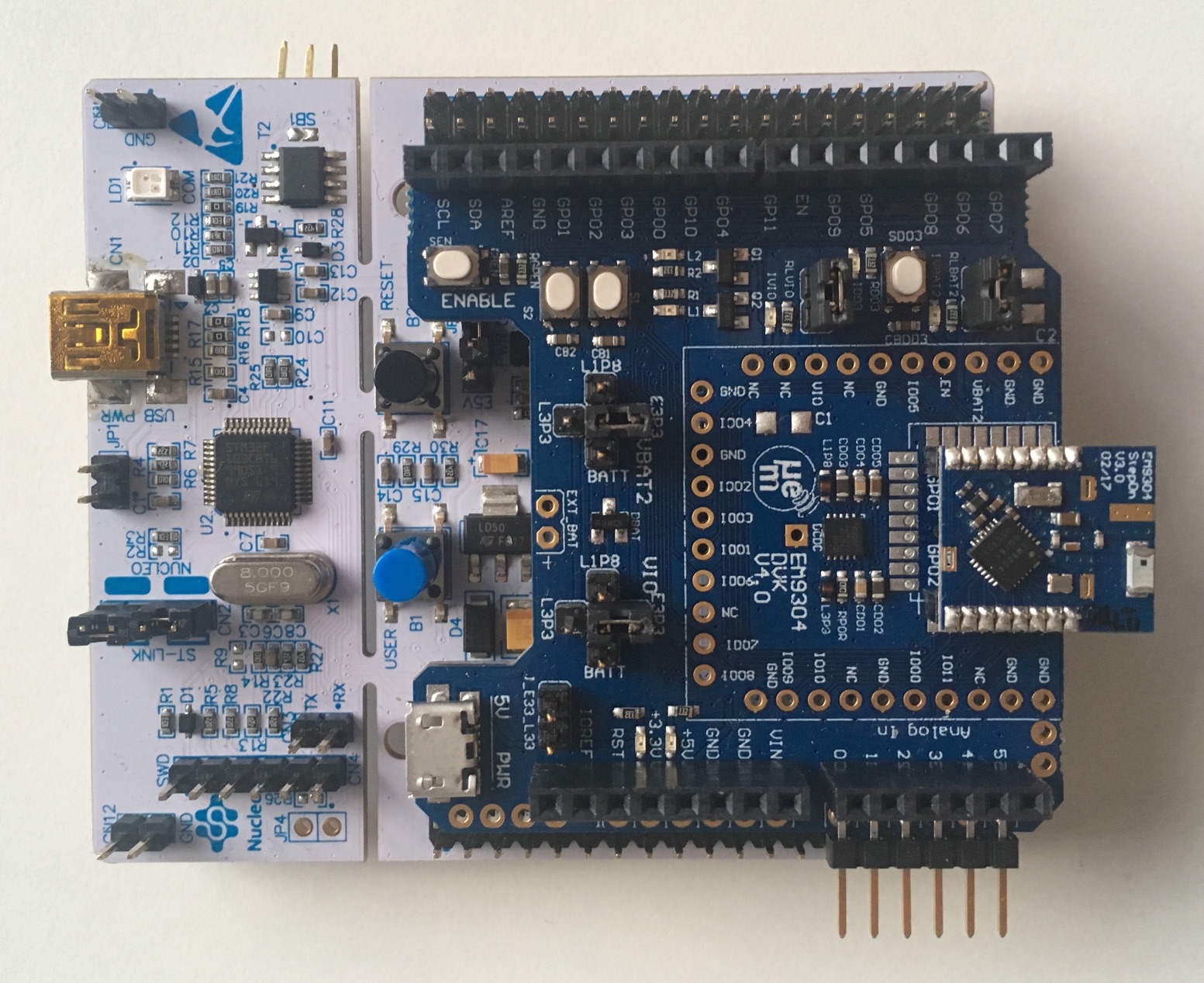
BTstack Port with Cinnamon for Semtech SX1280 Controller on Miromico FMLR-80
Cinnamon is BlueKitchen's minimal, yet robust Controller/Link Layer implementation for use with BTstack.
In contrast to common Link Layer implementations, our focus is on a robust and compact implementation for production use, where code size matters (e.g. current code size about 8 kB).
Overview
This port targets the Semtech SX1280 radio controller. The Host Stack and the Controller (incl. Link Layer) run on a STM32 MCU, with the SX1280 connected via SPI.
It uses the SX1280 C-Driver from Semtech to communicate with the SX1280. The main modification was to the SPI driver that uses DMA for full packets.
Status
Tested with the Miromico FMLR-80-P-STL4E module and our SX1280 Shield - see (port/stm32-l476rg-nucleo-sx1280). On the FMLR-80-P-STL4E module, the 52 Mhz clock for the SX1280 is controlled by the MCU.
SEGGER RTT is used for debug output, so a Segger J-Link programmer is required.
Uses 32.768 kHz crytstal as LSE for timing
Support for Broadcast and Peripheral roles.
The Makefile project compiles gatt_counter, gatt_streamer_server, hog_mouse and hog_keyboard examples.
Limitation
Advertising State:
- Only Connectable Advertising supported
- Only fixed public BD_ADDR of 33:33:33:33:33:33 is used
Connection State:
- Encryption not implemented
- Some LL PDUs not supported
Central Role:
- Not implemented
Observer Role:
- Not implemented
Low power mode - basically not implemented:
- MCU does not sleep
- SPI could be disabled during sleep
- 1 ms SysTick is used for host stack although 16-bit tick time is provided by LPTIM1 based on 32768 Hz LSE.
Getting Started
For the FMLR-80-P-STL4E module, just run make. You can upload the EXAMPLE.elf file created in build folder, e.g. with Ozone using the provided EXAMPLE.jdebug, and run it.
TODO
General
- indicate random address in advertising pdus
- allow to set random BD_ADDR via HCI command and use in Advertisements
- support other regular adv types
- handle Encryption
Low Power
- enter STANDY_RC mode when idle
- implement MCU sleep (if next wakeup isn't immediate)
- sleep after connection request until first packet from Central
- replace SysTick with tick counter based on LPTIM1
- disable SPI on MCU sleep
BTstack Port with Cinnamon for Semtech SX1280 Controller on STM32L476 Nucleo
Cinnamon is BlueKitchen's minimal, yet robust Controller/Link Layer implementation for use with BTstack.
In contrast to common Link Layer implementations, our focus is on a robust and compact implementation for production use, where code size matters (e.g. current code size about 8 kB).
Overview
This port targets the Semtech SX1280 radio controller. The Host Stack and the Controller (incl. Link Layer) run on a STM32 MCU, with the SX1280 connected via SPI.
It uses the SX1280 C-Driver from Semtech to communicate with the SX1280. The main modification was to the SPI driver that uses DMA for full packets.
Status
Tested with theMiromico FMLR-80-P-STL4E module (see port/stm32-l451-miromico-sx1280) and the STM32 L476 Nucleo dev kit with our SX1280 Shield.
SEGGER RTT is used for debug output, so a Segger J-Link programmer is required, but the on-board ST-Link programmer and debugger can be replaced by an SEGGER J-Link OB.
Uses 32.768 kHz crytstal as LSE for timing
Support for Broadcast and Peripheral roles.
The Makefile project compiles gatt_counter, gatt_streamer_server, hog_mouse and hog_keyboard examples.
Limitation
Advertising State:
- Only Connectable Advertising supported
- Only fixed public BD_ADDR of 33:33:33:33:33:33 is used
Connection State:
- Encryption not implemented
- Some LL PDUs not supported
Central Role:
- Not implemented
Observer Role:
- Not implemented
Low power mode - basically not implemented:
- MCU does not sleep
- SPI could be disabled during sleep
- 1 ms SysTick is used for host stack although 16-bit tick time is provided by LPTIM1 based on 32768 Hz LSE.
Getting Started
Just run make. You can upload the EXAMPLE.elf file created in build folder, e.g. with Ozone using the provided EXAMPLE.jdebug, and run it.
TODO
General
- indicate random address in advertising pdus
- allow to set random BD_ADDR via HCI command and use in Advertisements
- support other regular adv types
- handle Encryption
Low Power
- enter STANDY_RC mode when idle
- implement MCU sleep (if next wakeup isn't immediate)
- sleep after connection request until first packet from Central
- replace SysTick with tick counter based on LPTIM1
- disable SPI on MCU sleep
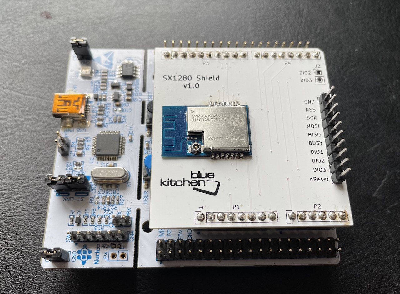
BTstack Port for STM32WB55 Nucleo Boards using FreeRTOS
This port supports the Nucleo68 and the USB dongle of the P-NUCLEO-WB55 kit. Both have 1 MB of Flash memory.
The STM32Cube_FW_WB_V1.3.0 provides the HAL and WPAN, and initializes the device and the initial Makefile. For easy development, Ozone project files are generated as well.
Hardware
In this port, the Nucelo68 or the USB Dongle from the P-NUCLEO-WB55 can be used.
Last test was done using FUS v1.2 and HCI BLE Firmware v1.13 on Nucleo68 See STM32Cube_FW_WB_V1.13.0/Projects/STM32WB_Copro_Wireless_Binaries/Release_Notes.html for firmware install instructions.
Note: Segger RTT is currently not really usable. When sleep modes ared disabled for debuggin (see port_thread()) RTT works, but the output buffer quickly overflows. In Block mode, radio stops working.
Nucleo68
The debug output is sent over USART1 and is available via the ST-Link v2.
USB Dongle
To flash the dongle, SWD can be used via the lower 6 pins on CN1: - 3V3 - PB3 - SWO (semi hosting not used) - PA14 - SCLK - PA13 - SWDIO - NRST - GND
The debug output is sent over USART1 and is available via PB6.
Software
FreeRTOS V10.2.0 is used to run stack, you can get this example version by checking out official repo:
$ cd Middlewares
$ git submodule add https://github.com/aws/amazon-freertos.git
$ git submodule update
& cd amazon-freertos && git checkout v1.4.8
Or by specifying path to FreeRTOS
$ make FREERTOS_ROOT=path_to_freertos
To build all examples, run make
$ make
All examples and the .jedbug Ozone project files are placed in the 'build' folder.
Flash And Run The Examples
The Makefile builds different versions: - example.elf: .elf file with all debug information - example.bin: .bin file that can be used for flashing
Nucleo68
There are different options to flash and debug the Nucleo68 board. The Nucleo68 boards comes with an on-board ST-Link programmer and debugger. As an alternative, the ST-Link programmer can be replaced by an SEGGER J-Link OB. Finally, the STM32 can be programmed with any ARM Cortex JTAG or SWD programmer via the SWD jumper.
USB Dongle
Please use any ARM Cortex SWD programmer via the SWD interface desribed in the hardware section.
Run Example Project using Ozone
When using an external J-Link programmer or after installing J-Link OB on the Nucleo68 board, you can flash and debug using the cross-platform SEGGER Ozone Debugger. It is included in some J-Link programmers or can be used for free for evaluation usage.
Just start Ozone and open the .jdebug file in the build folder. When compiled with "ENABLE_SEGGER_RTT", the debug output shows up in the Terminal window of Ozone. Note: as mentioned before, Segger RTT currently stops working when CPU2 has started up.
Debug output
All debug output can be either send via SEGGER RTT or via USART1. To get the console from USART1, simply connect your board under STLink-v2 to your PC or connect PB6 (USART1 TX) of the Nucleo board to an USB-2-UART adapter and open a terminal at 115200.
In src/btstack_config.h resp. in example/btstack_config.h of the generated projects, additional debug information can be enabled by uncommenting ENABLE_LOG_INFO.
Also, the full packet log can be enabled in src/btstack_port.c by uncommenting the hci_dump_init(..) line. The console output can then be converted into .pklg files for OS X PacketLogger or WireShark by running tool/create_packet_log.py
GATT Database
In BTstack, the GATT Database is defined via the .gatt file in the example folder. During the build, the .gatt file is converted into a .h file with a binary representation of the GATT Database and useful defines for the application.
BTstack on Web using WebSerial
This ports compiles BTstack into WebAssembly and allows to run it in a Chrome-based Browser. It communicates to the Bluetooth Controller via the WebSerial API.
Requirements
- Emscripten from https://emscripten.org
Build instructions
- Get Emscripten repository somewhere:
git clone https://github.com/emscripten-core/emsdk.git
- make sure EMSDK points to the root of your Emscripten installation:
export EMSDK=<path/to/your/emscripten/repository>
- create build folder and change to it:
mkdir ninjacd ninja
- configure:
cmake .. \
    -DCMAKE_TOOLCHAIN_FILE=$EMSDK/upstream/emscripten/cmake/Modules/Platform/Emscripten.cmake \
    -DCMAKE_BUILD_TYPE=Release
- build using your default CMake generator:
ninjaormake
Run Local Web Server
python3 -m http.server 8080
Test
- Open local URL
- Force refresh of .js files: CMD+Alt+R on Safari, CMD+Shift+R on Chrome
Supported Bluetooth Controllers
There's no chipset detection yet, so only Controllers that don't need configuration or firmware upload are supported: - Controllers with USB CDC and no need for firmware upload: - e.g. BL654 with Bluetooth SIG PTS Firmware - Controllers with regular UART that need for firmware upload: - e.g. Ezurio IF820/CYW20820 with HCI Firmware.
Status
Supported Controller start up and all examples work as expected.
BTstack Port for WICED platform
Tested with: - WICED SDK 3.4-6.2.1 - RedBear Duo: Please install RedBear WICED Add-On - Inventek Systems ISM4334x - Please contact Inventek Systems for WICED platform files - Inventek Systems ISM4343 (BCM43438 A1) - Please contact Inventek Systems for WICED platform files
To integrate BTstack into the WICED SDK, please move the BTstack project into WICED-SDK-6.2.1/libraries.
Then create projects for BTstack examples in WICED/apps/btstack by running:
./create_examples.py
Now, the BTstack examples can be build from the WICED root in the same way as other examples, e.g.:
./make btstack.spp_and_le_counter-RB_DUO
to build the SPP-and-LE-Counter example for the RedBear Duo (or use ISM43340_M4G_L44 / ISM4343_WBM_L151 for the Inventek Systems devices).
See WICED documentation about how to upload the firmware.
It should work with all WICED platforms that contain a Broadcom Bluetooth chipset.
The maximal baud rate is currenty limited to 1 mbps.
The port uses the generated WIFI address plus 1 as Bluetooth MAC address. It persists the LE Device DB and Classic Link Keys via the DCT mechanism.
All examples that rovide a GATT Server use the GATT DB in the .gatt file. Therefore you need to run ./update_gatt_db.sh in the apps/btstack/$(EXAMPLE) folder after modifying the .gatt file.
BTstack Port for Windows Systems with Bluetooth Controller connected via Serial Port
The Windows-H4 port uses the native run loop and allows to use Bluetooth Controllers connected via Serial Port.
Make sure to manually reset the Bluetooth Controller before starting any of the examples.
The port provides both a regular Makefile as well as a CMake build file. It uses native Win32 APIs for file access and does not require the Cygwin or mingw64 build/runtine. All examples can also be build with Visual Studio 2022 (e.g. Community Edition).
Configuration
Most Bluetooth Controllers connected via UART/H4 require some special configuration, e.g. to set the UART baud rate and/or to upload firmware patches during startup. The Windows-H4 port tries to detect the controller type automatically based on the reported manufacturer information. Here are some controller specific details:
TI CC256x
The CC256x needs the correct init script to start up. The build is configured to use bluetooth_init_cc2564C_1.5.c by default.
Please pick the correct one for your controller if needed. The application verifies that the selected init script matches the detected chipset, but the init script is linked into the executable.
Broadcom/Cypress/Infineon Controllers
Broadcom/Cypress/Infineon controllers require a PatchRAM file. The CMake build downloads the BCM43430 PatchRAM used e.g. on later Raspberry Pi models.
When running an example, provide the matching .hcd file in the current working directory.
Newer Infineon AIROC controllers like the CYW55xx series require AIROC Download Mode for PatchRAM upload. To enable it, provide --airoc-download-mode on the command line, for example:
gatt_counter.exe -u COM3 --airoc-download-mode
After opening the serial port, BTstack asks you to reset the controller and starts the firmware download after a short countdown.
Nordic Controller with HCI UART firmware
The main difference of Zephyr-based Nordic Bluetooth Controllers is that: - the nRF52- and nRF54-Series use 1000000 as baud rate instead of 115200 - they don't have a public BD_ADDR
You can use these with the regular windows-h4 port by setting the baudrate to 1000000, e.g. like this
gatt_counter.exe -u COM3 --baud 1000000
The fixed random static address is used automatically.
Visual Studio 2022
Visual Studio can directly open the provided port/windows-windows-h4/CMakeLists.txt and allows to compile and run all examples.
Visual Studio Code
The repository contains a shared VS Code workspace file for this port:
port/windows-h4/btstack-windows-h4.code-workspace
Open this workspace file in Visual Studio Code. It shows the full BTstack repository
in the file explorer, but configures CMake to use port/windows-h4/CMakeLists.txt
and places the build directory in port/windows-h4/build.
Setup
- Install the VS Code extensions
CMake ToolsandC/C++ - Install a C/C++ toolchain on Windows, e.g. Visual Studio Community or Build Tools
with the
Desktop development with C++workload - Make sure Python is installed, as some generated headers are created during the build
- Open
port/windows-h4/btstack-windows-h4.code-workspace
Build an example
- Open the Command Palette with
Ctrl+Shift+P - Run
CMake: Scan for Kits - Run
CMake: Select a Kit - Pick your Windows toolchain, e.g.
Visual Studio ... - amd64 - Run
CMake: Configure - Run
CMake: Select Build Target - Pick an example, e.g.
gatt_counter - Run
CMake: Build
The executable will be created in:
port/windows-h4/build/
Run an example
Open a terminal in Visual Studio Code, change to the build directory, and start the selected example, for example:
> cd port\windows-h4\build
> .\gatt_counter.exe
mingw64
It can also be compiles with a regular Unix-style toolchain like mingw-w64. mingw64-w64 is based on MinGW, which '...provides a complete Open Source programming tool set which is suitable for the development of native MS-Windows applications, and which do not depend on any 3rd-party C-Runtime DLLs.'
We've used the Msys2 package available from the downloads page on Windows 10, 64-bit and use the MSYS2 MinGW 64-bit start menu item to compile 64-bit binaries.
In the MSYS2 shell, you can install everything with pacman:
$ pacman -S git
$ pacman -S cmake
$ pacman -S make
$ pacman -S mingw-w64-x86_64-toolchain
$ pacman -S mingw-w64-x86_64-portaudio
$ pacman -S python
$ pacman -S winpty
Compilation with CMake
With mingw64-w64 installed, just go to the port/windows-h4 directory and use CMake as usual
$ cd port/windows-h4
$ mkdir build
$ cd build
$ cmake ..
$ make
Note: When compiling with msys2-32 bit and/or the 32-bit toolchain, compilation fails
as conio.h seems to be mission. Please use msys2-64 bit with the 64-bit toolchain for now.
Console Output
When running the examples in the MSYS2 shell, the console input (via btstack_stdin_support) doesn't work. It works in the older MSYS and also the regular CMD.exe environment. Another option is to install WinPTY and then start the example via WinPTY like this:
$ winpty ./gatt_counter.exe
The packet log will be written to hci_dump.pklg
BTstack Port for Windows Systems with DA14585 Controller connected via Serial Port
This port allows to use the DA14585 connected via Serial Port with BTstack running on a Win32 host system.
It first downloads the hci_585.hex firmware from the 6.0.8.509 SDK, before BTstack starts up.
Please note that it does not detect if the firmware has already been downloaded, so you need to reset the DA14585 before starting an example.
For production use, the HCI firmware could be flashed into the OTP and the firmware download could be skipped.
Tested with the official DA14585 Dev Kit Basic on OS X and Windows 10.
The port provides both a regular Makefile as well as a CMake build file. It uses native Win32 APIs for file access and does not require the Cygwin or mingw64 build/runtine. All examples can also be build with Visual Studio 2022 (e.g. Community Edition).
Visual Studio 2022
Visual Studio can directly open the provided port/windows-windows-h4-da14585/CMakeLists.txt and allows to compile and run all examples.
mingw64
It can also be compiles with a regular Unix-style toolchain like mingw-w64. mingw64-w64 is based on MinGW, which '...provides a complete Open Source programming tool set which is suitable for the development of native MS-Windows applications, and which do not depend on any 3rd-party C-Runtime DLLs.'
We've used the Msys2 package available from the downloads page on Windows 10, 64-bit and use the MSYS2 MinGW 64-bit start menu item to compile 64-bit binaries.
In the MSYS2 shell, you can install everything with pacman:
$ pacman -S git
$ pacman -S cmake
$ pacman -S make
$ pacman -S mingw-w64-x86_64-toolchain
$ pacman -S mingw-w64-x86_64-portaudio
$ pacman -S python
$ pacman -S winpty
Compilation with CMake
With mingw64-w64 installed, just go to the port/windows-h4 directory and use CMake as usual
$ cd port/windows-h4
$ mkdir build
$ cd build
$ cmake ..
$ make
Note: When compiling with msys2-32 bit and/or the 32-bit toolchain, compilation fails
as conio.h seems to be mission. Please use msys2-64 bit with the 64-bit toolchain for now.
Console Output
When running the examples in the MSYS2 shell, the console input (via btstack_stdin_support) doesn't work. It works in the older MSYS and also the regular CMD.exe environment. Another option is to install WinPTY and then start the example via WinPTY like this:
$ winpty ./gatt_counter.exe
The packet log will be written to hci_dump.pklg
BTstack Port for Windows Systems with Zephyr-based Controller
This port has been moved to port/archive/windows-h4-zephyr.
Zephyr-based Controllers are supported by the regular windows-h4 port. Use baudrate 1000000, e.g.:
./gatt_counter.exe -u COM3 --baud 1000000
BTstack Port for Windows Systems using the WinUSB Driver
The Windows-WinUSB port uses the native run loop and WinUSB API to access a USB Bluetooth dongle.
The port provides both a regular Makefile as well as a CMake build file. It uses native Win32 APIs for file access and does not require the Cygwin or mingw64 build/runtine. All examples can also be build with Visual Studio 2022 (e.g. Community Edition).
Access to Bluetooth USB Dongle with Zadig
To allow WinUSB to access an USB Bluetooth dongle, you need to install a special device driver to make it accessible to user space processes.
It works like this:
- Download Zadig
- Start Zadig
- Select Options -> “List all devices”
- Select USB Bluetooth dongle in the big pull down list
- Select WinUSB in the right pull down list
- Select “Replace Driver”
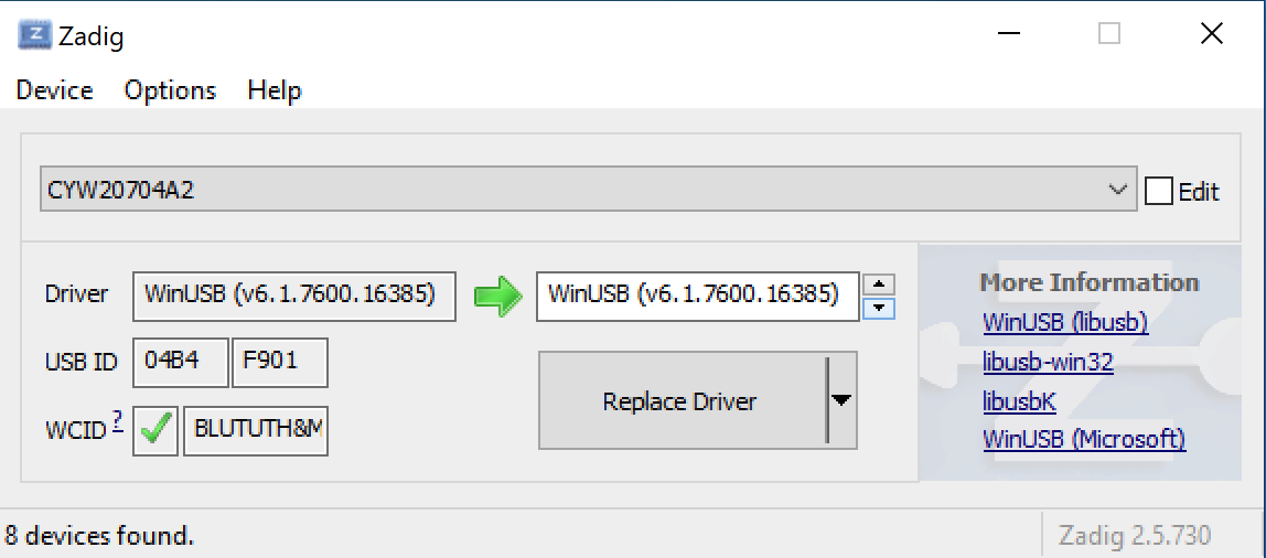
After the new driver was installed, your device is shown in the Device Manager with Device Provider 'libwdi'
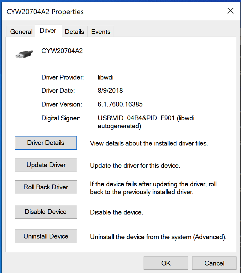
Visual Studio 2022
Visual Studio can directly open the provided port/windows-winusb/CMakeLists.txt and allows to compile and run all examples.
For this, the C++ CMake tools for Windows is required. They are part of the Desktop development with C++ workloads.
mingw64
It can also be compiles with a regular Unix-style toolchain like mingw-w64. mingw64-w64 is based on MinGW, which '...provides a complete Open Source programming tool set which is suitable for the development of native MS-Windows applications, and which do not depend on any 3rd-party C-Runtime DLLs.'
In the MSYS2 shell, you can install everything with pacman:
$ pacman -S git
$ pacman -S cmake
$ pacman -S make
$ pacman -S mingw-w64-x86_64-toolchain
$ pacman -S mingw-w64-x86_64-portaudio
$ pacman -S python
$ pacman -S winpty
Compilation with CMake
With mingw64-w64 installed, just go to the port/windows-h4 directory and use CMake as usual
$ cd port/windows-h4
$ mkdir build
$ cd build
$ cmake ..
$ make
Note: When compiling with msys2-32 bit and/or the 32-bit toolchain, compilation fails
as conio.h seems to be mission. Please use msys2-64 bit with the 64-bit toolchain for now.
Console Output
When running the examples in the MSYS2 shell, the console input (via btstack_stdin_support) doesn't work. It works in the older MSYS and also the regular CMD.exe environment. Another option is to install WinPTY and then start the example via WinPTY like this:
$ winpty ./spp_and_le_counter.exe
BTstack Port for Windows Systems with Intel Wireless 8260/8265 Controllers
Same as port/windows-winusb, but customized for Intel Wireless 8260 and 8265 Controllers. These controller require firmware upload and configuration to work. Firmware and config is downloaded from the Linux firmware repository.
The port provides both a regular Makefile as well as a CMake build file. It uses native Win32 APIs for file access and does not require the Cygwin or mingw64 build/runtine. All examples can also be build with Visual Studio 2022 (e.g. Community Edition).
Access to Bluetooth USB Dongle with Zadig
To allow WinUSB to access an USB Bluetooth dongle, you need to install a special device driver to make it accessible to user space processes.
It works like this:
- Download Zadig
- Start Zadig
- Select Options -> “List all devices”
- Select USB Bluetooth dongle in the big pull down list
- Select WinUSB in the right pull down list
- Select “Replace Driver”
After the new driver was installed, your device is shown in the Device Manager with Device Provider 'libwdi'
Visual Studio 2022
Visual Studio can directly open the provided port/windows-winusb-intel/CMakeLists.txt and allows to compile and run all examples.
mingw64
It can also be compiles with a regular Unix-style toolchain like mingw-w64. mingw64-w64 is based on MinGW, which '...provides a complete Open Source programming tool set which is suitable for the development of native MS-Windows applications, and which do not depend on any 3rd-party C-Runtime DLLs.'
In the MSYS2 shell, you can install everything with pacman:
$ pacman -S git
$ pacman -S cmake
$ pacman -S make
$ pacman -S mingw-w64-x86_64-toolchain
$ pacman -S mingw-w64-x86_64-portaudio
$ pacman -S python
$ pacman -S winpty
Compilation with CMake
With mingw64-w64 installed, just go to the port/windows-h4 directory and use CMake as usual
$ cd port/windows-h4
$ mkdir build
$ cd build
$ cmake ..
$ make
Note: When compiling with msys2-32 bit and/or the 32-bit toolchain, compilation fails
as conio.h seems to be mission. Please use msys2-64 bit with the 64-bit toolchain for now.
Console Output
When running the examples in the MSYS2 shell, the console input (via btstack_stdin_support) doesn't work. It works in the older MSYS and also the regular CMD.exe environment. Another option is to install WinPTY and then start the example via WinPTY like this:
$ winpty ./gatt_counter.exe
The packet log will be written to hci_dump.pklg
BTstack Port for Zephyr RTOS
Overview
This port targets any platform supported by Zephyr that either contains a built-in Bluetooth Controller
or is connected to an external Controller via one of the supported Zephyr HCI Transports drivers (see zephyr/drivers/bluetooth/hci)
Status
Tested with nRF52 DK (PCA10040), nRF52840 DK (PC10056) and nRF5340 DK (PCA10095) boards only. It uses the fixed static random BD ADDR stored in NRF_FICR/NRF_FICR_S, which will not compile on non nRF SoCs.
Build Environment
The first step needs to done once. Step two is needed every time to setup the environment.
1. Build Environment Preconditions
Follow the getting started guide until you are able to build an example.
Then update the ZEPHYR_ROOT variable in env.sh to point to your zephyrproject. Defaults to ~/zephyrproject
2. Prepare the build environment
To setup your environment to build a BTstack example, run the provided setup in env.sh.
source env.sh
Building and Running on nRF52840
1. Build Example
You can build an example using:
west build -b nrf52840dk/nrf52840
nrf52840dk/nrf52840 selected the Nordic nRF52840 DK. For the older nRF52 DK with nRF52832, you can specify nrf52dk/nrf52832.
To get a list of all supported Zephyr targets, run west boards
To change zephyr platform settings use:
west build -b nrf52840dk/nrf52840 -t menuconfig
To build a different example, e.g. the gatt_streamer_server, set the EXAMPLE environment variable:
EXAMPLE=gatt_streamer_server west build -b nrf52840dk/nrf52840
2. Flash Example
To flash a connected board:
west flash
Building and Running on nRF5340
The nrf5340 is a dual core SoC, where one core is used for Bluetooth HCI functionality and the other for the high level application logic. So both cores need to be programmed separately. Using the nRF5340-DK for example allows debug output on both cores to separate UART ports. For the nRF5340 a network core firmware is required, which one depends on the use-case. With 2. an options is given.
1. Building the application
build using:
west build -b nrf5340dk/nrf5340/cpuapp
with debug:
west build -b nrf5340dk/nrf5340/cpuapp -- -DOVERLAY_CONFIG=debug_overlay.conf
2. Using zephyr network core image
the hci_rgmsg application needs to be loaded first to the network core.
Configure network core by selecting the appropriate config file, for example nrf5340_cpunet_iso-bt_ll_sw_split.conf.
additionally it's required to increase the main stack size from
CONFIG_MAIN_STACK_SIZE=512
to
CONFIG_MAIN_STACK_SIZE=4096
then the network core image can be compiled and flashed
west build -b nrf5340dk/nrf5340/cpunet -- -DCONF_FILE=nrf5340_cpunet_iso-bt_ll_sw_split.conf
west flash
or with debugging
west build -b nrf5340dk/nrf5340/cpunet -- -DCONF_FILE=nrf5340_cpunet_iso-bt_ll_sw_split.conf -DOVERLAY_CONFIG=debug_overlay.conf
west flash
Build and Running on STM32 Nucleo 144 board with Ezurio M.2 Adapter and M.2 Bluetooth Controller
Ezurio's Wi-Fi M.2 2230 to STM32 Nucleo Adapter Card allows to connect any Bluetooth/Wifi M.2 Card to most STM32 Nucleo-144 boards. M.2 modules are available from multiple module vendors, e.g. Ezurio, u-blox, and Embedded Artists.
The adapter board takes care of 3.3V and 1.8V translation and routes SDIO for Wifi and UART for Bluetooth to the Nucleo board.
On most Nucleo-144 boards, the Bluetooth UART ends up on the same STM32, namely: PD3-PD6.
See port/zephyr/boards/shields/ezurio_m2_nucleo_144_adapter.overlay for details.
We tested CYW55513 and CYW55573 M.2 modules with the following boards:
| Nucleo board | Working |
|---|---|
| nucleo_f439zi | x |
| nucleo_h753zi | x |
| nucleo_h563zi | x |
| nucleo_h755zi |
The PatchRAM .hcd files can be placed in the project folder and specified by the CONFIG_AIROC_CUSTOM_FIRMWARE_HCD_BLOB
option in the corresponding boards/$BOARD.conf file.
1. Build Example
west build -b nucleo_f439zi --shield ezurio_m2_nucleo_144_adapter
west build -b nucleo_h755zi_q/stm32h755xx/m7 --shield ezurio_m2_nucleo_144_adapter
TODO
- Allow/document use of Zephyr HCI Drivers