MSP432P401R + CC2564C Port: UART without Hardware RTS/CTS Flow Control
When using Bluetooth Controllers via the H4/UART transport, there’s no error-correction mechanism. Therefore, a single lost byte causes the HCI transport to loose synchronization and requires a full Controller reboot.
An effective way to prevent loosing bytes on the UART peripheral is to enable hardware CTS/RTS flow control. For example, most STM32 MCUs have a rather simple, yet effective implementation: – when a byte is received, the RTS line raises causing the Bluetooth Controller to pause output; – when the UART’s receive register is read, the RTS line is lowered again.
In this blog post, we will look at UART peripherals that lack hardware RTS/CTS flow control. We will use the MSP432P401 as an example, which combines an ARM Cortex M4F with the UART peripheral from the MSP430 line of MCU.
Bluetooth HCI Packet Reception on UART/H4
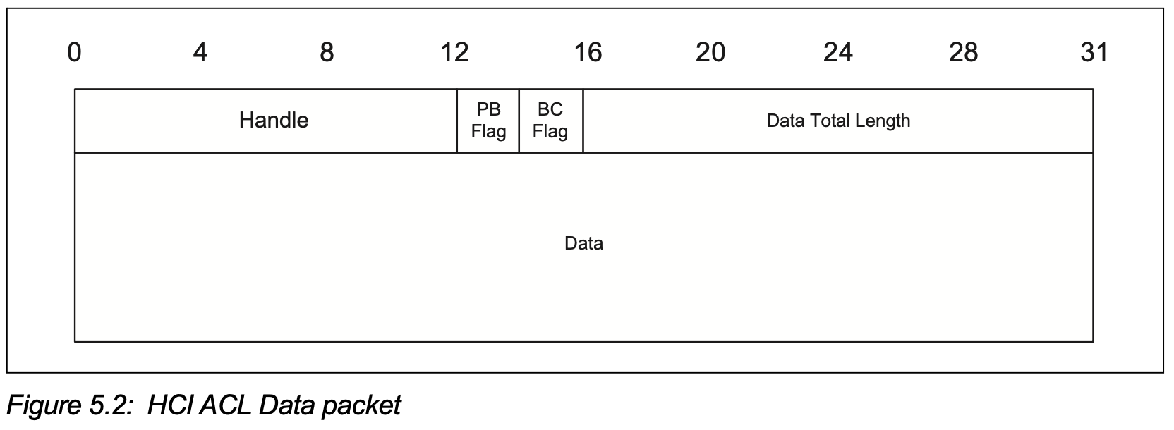
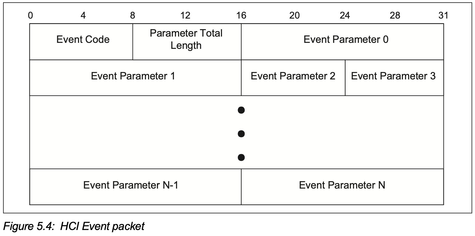
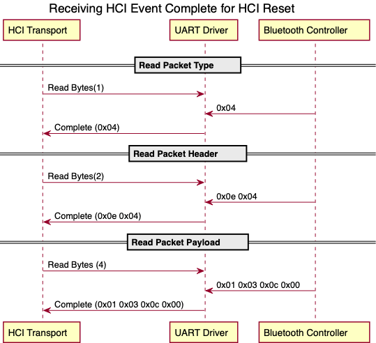
There are several types of Bluetooth HCI packets that can be received. Let’s look at two of them: HCI ACL Data and HCI Event packet. Each of these have a different header length: 4 bytes for ACL packets and 2 bytes for Events, see below.
|
|
As the headers of HCI packet types differ in size, a Bluetooth stack needs to issue three requests to read a single packet from the UART:
- read packet type
- read packet header to get the payload length
- read payload
To support the read requests from UART, a BTstack target port must implement the hal_uart_block.h API. Here are the relevant functions:
...
// Init driver
void hal_uart_dma_init(void);
// Set baudrate
int  hal_uart_dma_set_baud(uint32_t baud);
// Send block
void hal_uart_dma_send_block(const uint8_t *buffer, uint16_t length);
// Receive block
void hal_uart_dma_receive_block(uint8_t *buffer, uint16_t len);
...
The hal_uart_block.h API directly maps to a DMA-based driver that lets the DMA engine read the requested bytes before notifying the driver. Alternatively, a minimal single-byte IRQ driver can be used as well. In both cases, the received data can be directly written to the provided buffer resulting in an efficient zero-copy implementation.
HCI Packet Reception on UART Peripheral without RTS/CTS
While the hal_uart_block.h API approach works well with hardware RTS/CTS, any unexpected delay in the IRQ handler of both driver types can cause an UART overrun if there’s no hardware flow control. Because of this, a different approach is required for MCUs without RTS/CTS.
The main idea is to combine following three tasks:
- Task 1: continuously receive data from the UART into a ring buffer,
- Task 2: pause incoming data to prevent a buffer overrun by controlling RTS, and
- Task 3: transfer data from the ring buffer into the provided HCI packet buffer.
A good overview/introduction is given by this STM32 Application Note AN3109
Let’s look at the three tasks.
Task 1: Continuously Receive Data
Continuously receiving data without loosing a byte is the main responsibility of a DMA controller, which is available in most MCUs. The DMA engine usually can be configured to read a number of bytes from the UART RX buffer and store them in a provided memory buffer (Peripheral to Memory transfer).
In addition to basic transfers, most MCUs also provide special modes that allow to continuously receive data. Some controllers support a circular mode, where the DMA restarts after the last receive byte, e.g. on most STM32 MCUs. In this mode, two different IRQs are generated: transfer half-complete and transfer complete IRQ. A transfer half-complete IRQ is generated after the first half of the transfer is complete, and transfer complete IRQ is generated after the transfer is complete. Upon complete IRQ, the DMA engine will automatically restart to receive data at the beginning of the buffer again.
On our MSP432P401R, the DMA engine can be configured into a ping-pong mode that allows to setup a transfer in advance, such that it automatically starts when the current one is complete, without loosing a single byte.
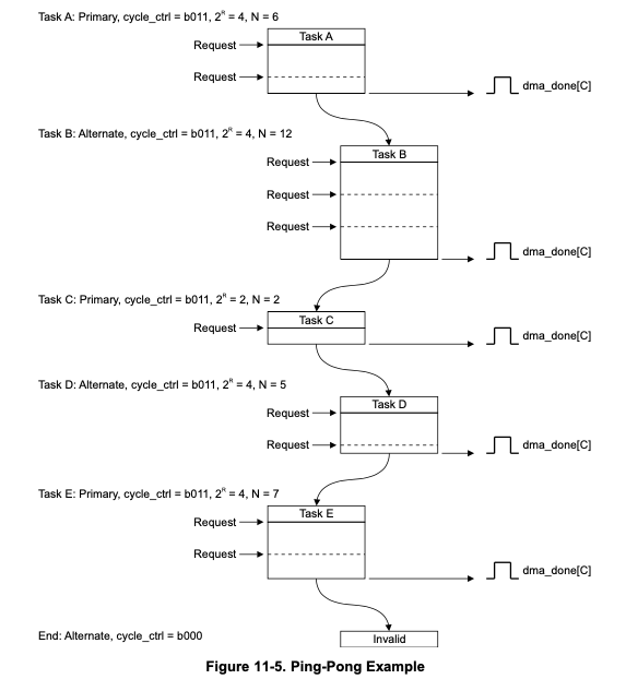
When using two buffers A and B that are next to each other in memory, this resembles the circular mode of the STM32. Other MCUs have similar concepts.
For the rest of this artice, we will assume that there are buffers A and B available and a transfer complete IRQ is generated when one of the buffers was filled by DMA.
Task 2: Pause Incoming Data
With the ability to continuously receive data, we need to make sure that data is processed before new data overwrites it. For this, we need to raise RTS to pause the Bluetooth Controller, until enough data has been consumed. The transfer complete IRQs are a natural place to implement this. When buffer A was written and the transfer complete IRQ is triggered, we can raise RTS and can be sure that the Bluetooth Controller stops transmitting before buffer B will be full as well. When buffer A is fully processed and ready for new data, RTS can be de-asserted again. See here:

Task 3: Transfer Data
In the STM32 Application Note AN3109, data of unknown length is received, so a timeout is required to detect that the packet is complete. For Bluetooth H4, the stack always requests a number of bytes, so there’s no need for an Rx Idle timeout. Here, it is sufficient to periodically transfer data from the circular buffer into the BTstack request buffer. To keep the logic simple and robust, in this port, we call a transfer function both from the half and complete IRQs as well as from the SysTick 1ms IRQ.
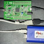
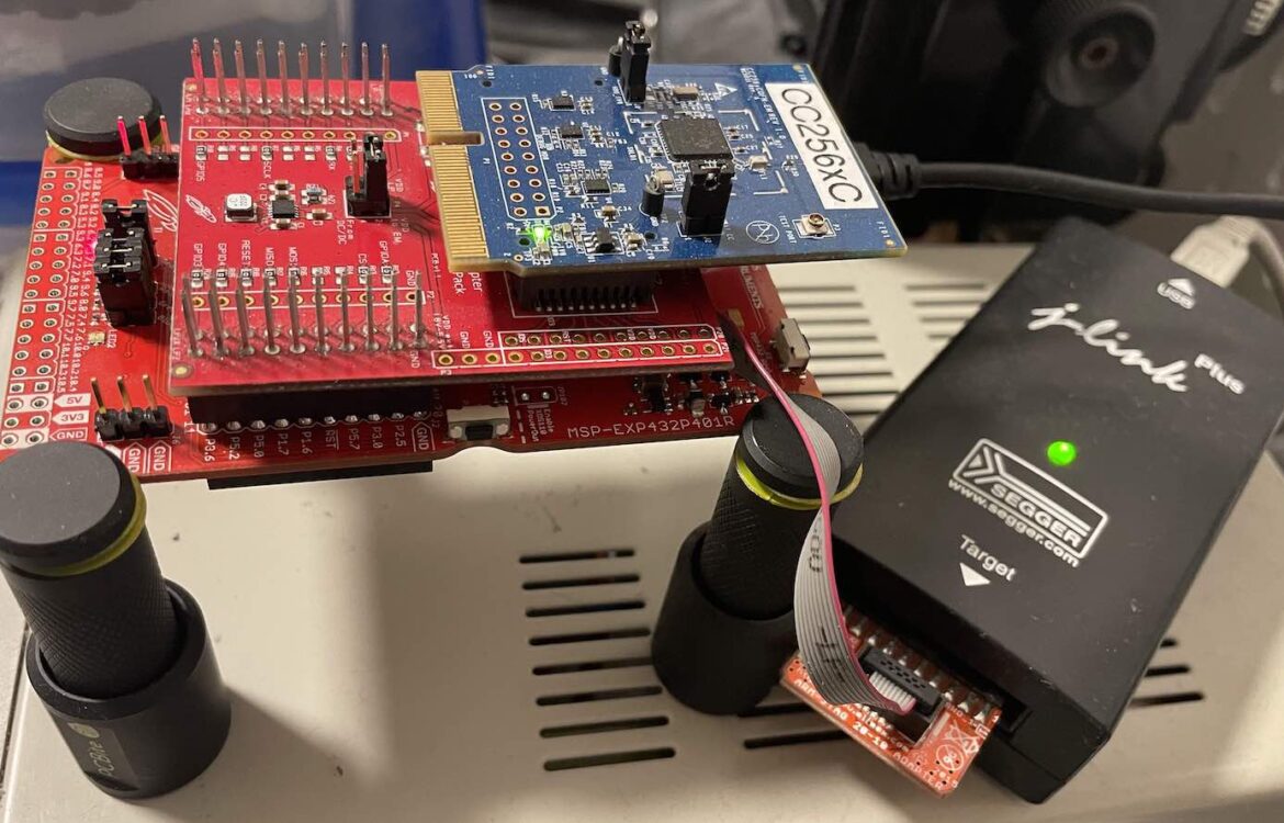
Hardware
For this port, we’ve used the following hardware: TI MSP432P401R LaunchPad.
The maximum MCU speed is 48 MHz. With the 16-times oversampling mode, the UART can be configured for 3 mbps. At this speed, 64 bytes are received in 20 us.
As Bluetooth Controller, there are two BoosterPacks that can be used:
- BOOST-CC2564MODA CC2564B BoosterPack (USD 20)
-
Evaluation Module (EM) Adaptor (USD 20) with one of the CC256x modules:
The CC2564B Boosterpack is around USD 20 while the EM Adapter with the CC2564C module is around USD 80. There’s even a bundle consisting of the MSP432P401 Launchpad and the CC2564B Boosterpack available for USD 40.
The project in the BTstack repo `port/msp432p401lp-cc256x’ is configured for the EM Adapter + newer CC2564C module.
When using the CC2564B (either as BOOST-CC2564MODA or CC2564B Dual-mode Bluetooth® Controller Evaluation Module), the bluetooth_init_cc2564B_1.8_BT_Spec_4.1.c must be used as cc256x_init_script. See Makefile variable INIT_SCRIPT.
When using the CC2564B Booster Pack, please uncomment the defines for the GPIO definition (search for BOOST-CC2564MODA).
When using the EM Adapter Booster Pack, please make sure to solder a 32.768 kHz quarz oscillator as explained in 4.7 of the EM Wireless Booster Pack User Guide. If you don’t have an oscillator of that size, you might solder one upside done (turtle-on-back style) to the unused upper right pad and wire GCC, VCC, and clock with thin wires.
Development Tools
We’ve used the J-Link Plus to flash and debug the MSP432P401 LaunchPad. For this, we’ve removed the jumpers 3-10 (RXD-TDI) from J101 and plugged the debugger in J8 (MSP432 In).
As usual, Salea’s Logic 16 was used to verify the UART behavior, including the manually controlled RTS line, and also to visualize timing behavior by toggling a GPIO pin.
Software
We’ve used the UART example of the TI Driverlib from the SimpleLink MSP432-MSP432-SDK v3.40.01.02 as basis and used the Segger J-Link Plus with an ARM Cortex adapter. The J-Link Plus allowed to use Segger RTT for debug output, as with most of our ports.
UART Driver
The approach sketched above works fine and does not require much code. It should be possible to adapt it for other MCUs without hardware RTS/CTS as well.
The main variables are hal_dma_rx_active_buffer and hal_dma_rx_offset which indicate the the current buffer and read offset. The current HCI Read request is stored as rx_buffer_ptr and bytes_to_read.
The two interesting functions are:
hal_uart_dma_update_rtsfunctionhal_uart_dma_harvestfunction
The hal_uart_dma_update_rts function checks which buffer (A or B) the DMA engine is currently written to, and if this differs from the buffer that data is read from, it raises RTS. As an example, when transfer A is complete and transfer B becomes active, while there’s still data in buffer A, RTS is raised. Otherwise, RTS is de-asserted. It is called on transfer complete IRQ (for A or B) and when hal_uart_dma_harvest did fully process a buffer.
void hal_uart_dma_update_rts(void){
    // get active transfer
    uint32_t attribute = MAP_DMA_getChannelAttribute(DMA_CH5_EUSCIA2RX & 0x0F);
    uint8_t  active_transfer_buffer = (attribute & UDMA_ATTR_ALTSELECT) ? 1 : 0;
    if (hal_dma_rx_active_buffer == active_transfer_buffer){
        GPIO_setOutputLowOnPin(BLUETOOTH_CTS_PORT, BLUETOOTH_CTS_PIN);
    } else {
        GPIO_setOutputHighOnPin(BLUETOOTH_CTS_PORT, BLUETOOTH_CTS_PIN);
    }
}
The job of hal_uart_dma_harvest function is to transfer data from the current buffer (hal_dma_rx_active_buffer) into the request buffer. If the current buffer is fully processed, hal_uart_dma_update_rts is called, which in turn de-asserts RTS. If the request is complete, the higher layer driver is notified. It is called form the the SysTick handler, the transfer complete IRQs and from the hal_uart_dma_receive_block implementation.
// directly called from timer or similar interrupt.
// to call from non-isr context, interrupts must be disabled
void hal_uart_dma_harvest(void){
    if (bytes_to_read == 0) {
        return;
    }

    uint16_t bytes_avail = hal_dma_rx_bytes_avail(hal_dma_rx_active_buffer, hal_dma_rx_offset);
    if (bytes_avail == 0) {
        return;
    }

    // fetch bytes from current buffer
    uint16_t bytes_to_copy = btstack_min(bytes_avail, bytes_to_read);
    memcpy(rx_buffer_ptr, &hal_dma_rx_ping_pong_buffer[hal_dma_rx_active_buffer * HAL_DMA_RX_BUFFER_SIZE + hal_dma_rx_offset], bytes_to_copy);
    rx_buffer_ptr     += bytes_to_copy;
    hal_dma_rx_offset += bytes_to_copy;
    bytes_to_read     -= bytes_to_copy;

    // if current buffer fully processed, restart DMA transfer and switch to next buffer
    if (hal_dma_rx_offset == HAL_DMA_RX_BUFFER_SIZE){
        hal_dma_rx_offset = 0;
        hal_dma_rx_start_transfer(hal_dma_rx_active_buffer);
        hal_dma_rx_active_buffer = 1 - hal_dma_rx_active_buffer;
        hal_uart_dma_update_rts();
    }

    if (bytes_to_read == 0){
        (*rx_done_handler)();
    }
}
Issues and Other Surprises
During the port, we’ve run into a few unexpected issues we’ve had to overcome and which we’d like to share here:
- linker script lacks Entry Point, and
- baud rate incorrect after reset with debugger
Linker script lacks Entry Point
After compiling the provided UART example (uart_pc_echo_12mhz_brclk), uploading with Ozone/J-Link worked, but a HardFault occurred right away. Even placing a breakpoint in the Reset routine didn’t help. Right after Reset, the PC points to the function __do_global_dtors_aux. Calling the destructor even before main was ever reached seems weird.
Weirdly, when manually resetting the MSP432, e.g. via the physical Reset button on the LaunchPad, the example did start and run as expected.
After some research, we’ve learned that Segger’s Ozone debugger uses ENTRY value from the .elf file to set the Program Counter after Reset (at least in the default configuration). However, for unknown reasons, most linker scripts provided in the SimpleLink SDK lack this entry. For the mentioned example, it’s therefore sufficient to add
...
/* Entry Point */
ENTRY(resetISR);
...
to the linker script to make it work with Ozone as well.
Baud rate incorrect after reset with debugger
When getting used to the UART driver, we’ve realized that the baud rate was occasionally incorrect. It wasn’t totally random, it was just half the expected rate. This happened when the Reset was triggered by the debugger. The baud rate was correct, if the MCU was powered up or reset via the physical Reset button. Following the assumption that the most likely case is a misconfiguration of the peripherals, we carefully compared the register values for the system clocks as well as for the UART for both setups. Eventually, we detected that the register CS->CTL1 is not set to the default value from the data sheet (it shows 0x10000033 instead of 0x00000033).
While it’s unclear, why this happens, the simplest fix was to explicitly reset this register in the start up code in system_msp432p401r.c to the documented default value.
void SystemInit(void){
    ...
    CS->CTL1 = 0x00000033;   // reset value (SMCLK, HSMCLK, MCLK source DCO)
    ...
}