Making Your Own Adapters

For quite some time, I’ve envied people that made their own PCB boards to solve simple connectivity problems instead of using solderless breadboards or creating some ugly and non-robust one-off solder sins. While a decade ago, creating PCB was either expensive or involved toxic chemicals for the DIY path, companies like Oshpark, Fritzing Fab, or SeeedStudio Fusion solve this problem by providing small PCB for a few bucks.
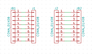
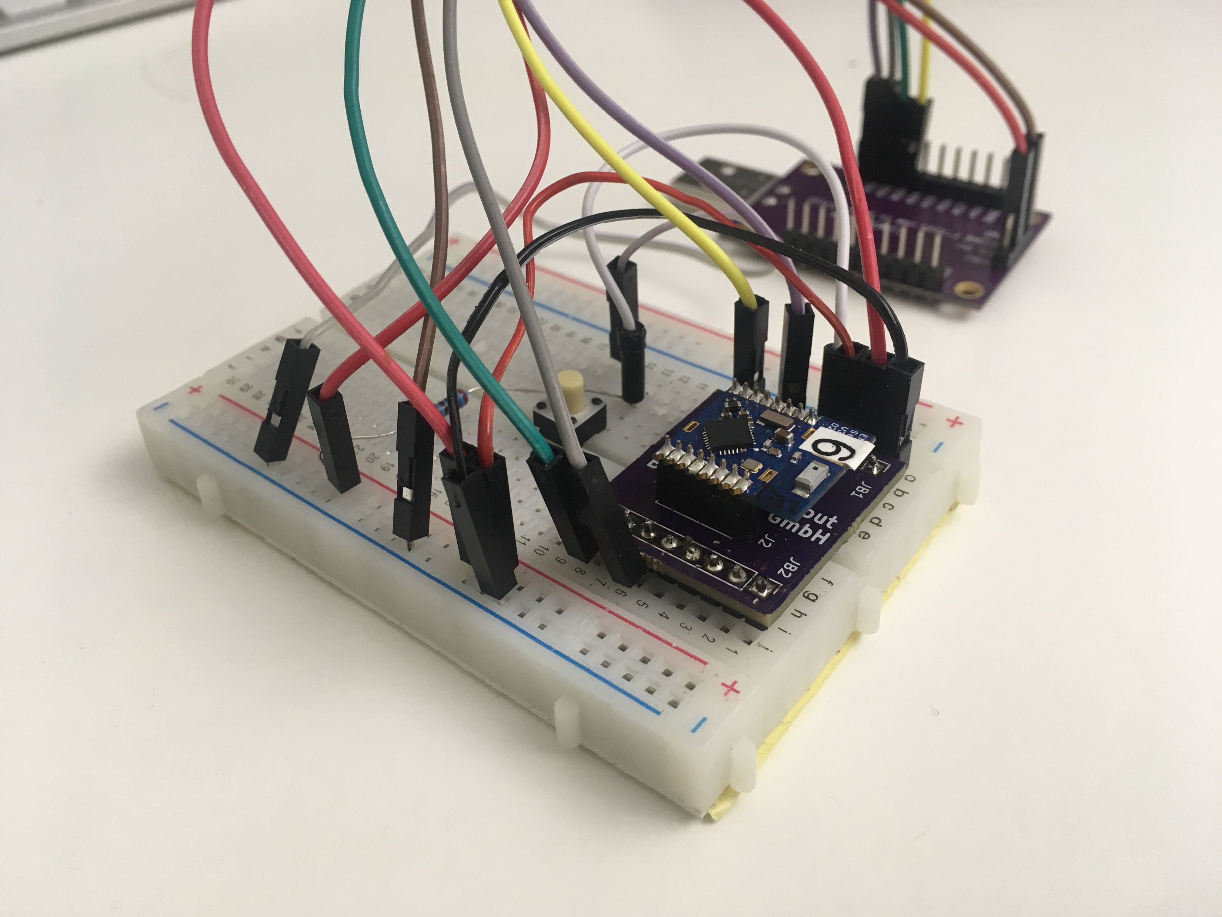
Now, we just need to design the board. Recently, I needed a simple board to break out all lines of a 0.05″ DIP module. With help of a friend, it didn’t take long to add two 0.05″ and two 0.1″ connectors, connect them one by one, plus route all connections manually for fun in KiCad.
|
|
If you need one, all files are here or can be ordered at OSHpark.
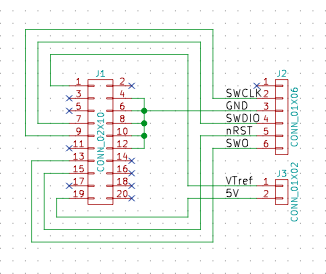
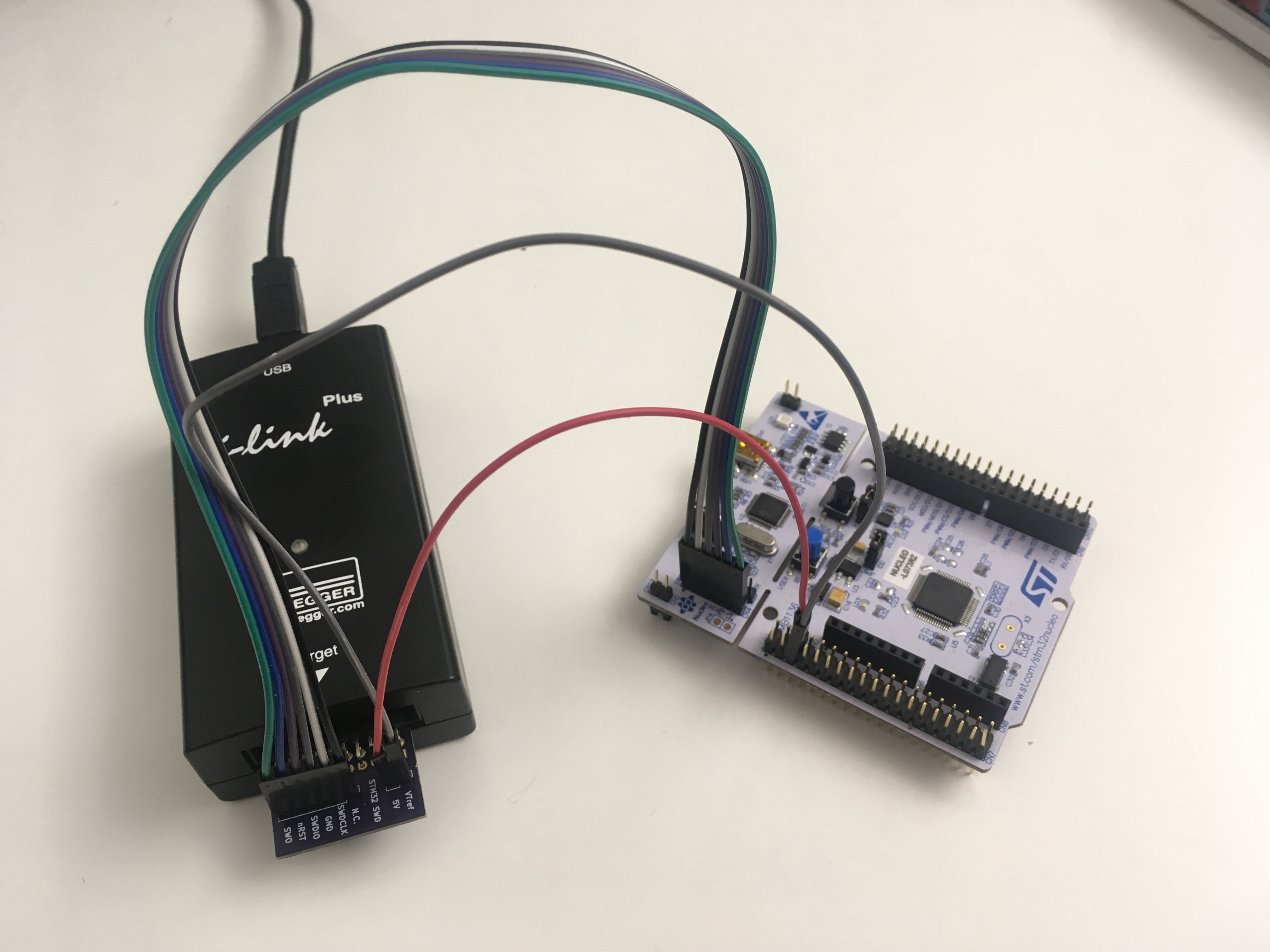
Some time later, I wanted to use a SEGGER J-Link Plus with an STM32 development board which only has a proprietary 6-pin SWD debug interface. While it’s possible to connect them with jumper wires, nobody seems to be bothered by this – or just uses either the built-in ST-Link/V2 debugger or upgraded it to the free J-Link version – at least I couldn’t find a commercial adapter for it. With my new knowledge, I’ve managed to place a few 0.1″ connectors on a PCB and got a working adapter.
|
|
Similar, files are here and boards can be ordered at OSHpark.
As you might have noticed, the adapters don’t have any components asides from pin headers. I guess the next tiny step could be a PCB with a few pull-up resistors 🙂
