BTstack Port for STM32 F4 Discovery Board with CC256x
In our first post we’ll describe, in a (mostly) linear fashion, how we ported BTstack to the STM32 platform. The steps we took to port BTstack could be easily generalized, so this example should serve as well as a tutorial for porting BTstack to other platforms.
Hardware Overview
For this port, we will get BTstack up and running on some ready-to-use hardware without soldering or too much jumper wires.
Bluetooth chipsets are usually available as a single chip where you’d need to copy some RF design from the datasheet, create a PCB and hope that it will work, or, use some industrial Bluetooth modules that also require a custom PCB to connect it to any MCU development kit.
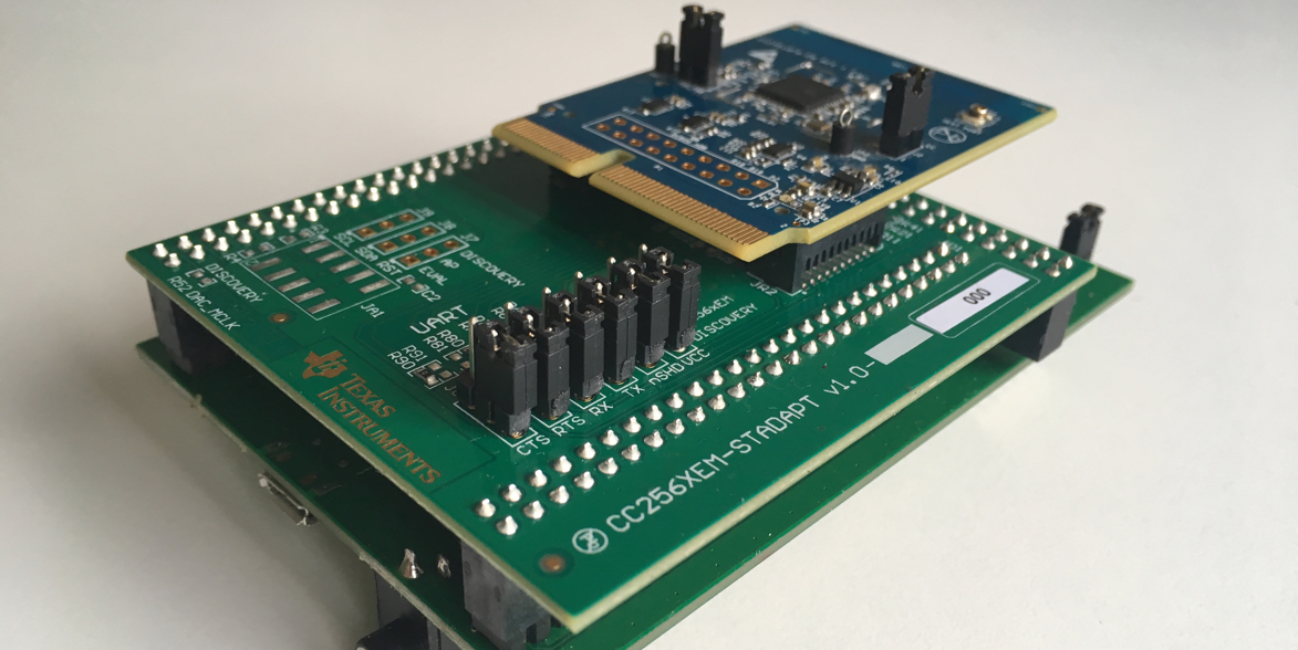
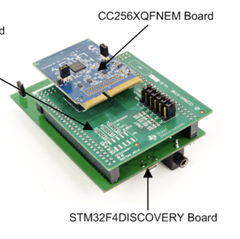
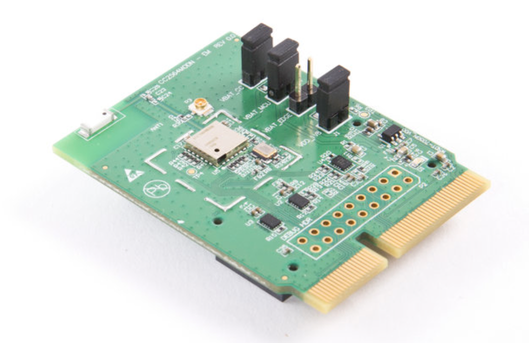
Traditionally, TI provides their CC256x Bluetooth Controller as pluggable evaluation modules (called ETU – Easy-To-Use) for their 16-bit and 32-bit development kits. In an effort to promote their use with STM32 MCUs, TI created an adapter board that allows to use the CC256x module with the STM32 F4 Discovery board (and the STM3240G-EVAL Board). Plugged together, it looks like this:
|
It clearly doesn’t win a price for elegance, but it does avoid soldering. Note that the Discovery board is shown face-down. Otherwise, the CC256x module could wiggle out of the connector when the STM32 faces upside.
So we have:
|
|
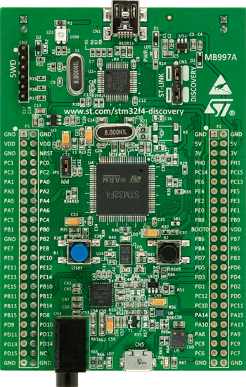
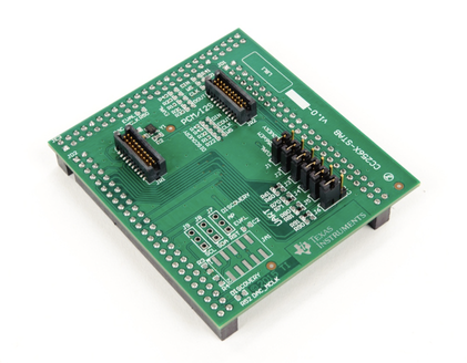
| STM32 F4 Discovery Board | CC256xEM Bluetooth Adapter Kit for ST |
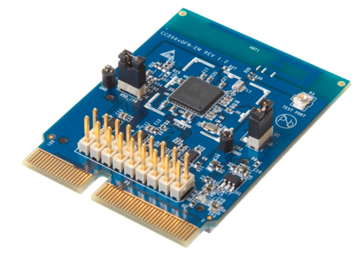
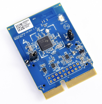
In this set, we can plug any of these CC256x Bluetooth modules:
|
|
|
| Dual-mode Bluetooth® CC2564 module evaluation board | CC2564B Dual-mode Bluetooth® Controller Evaluation Module | CC2564C Dual-mode Bluetooth® Controller Evaluation Module |
The first module with the older CC2564B is around USD 20 and has a green PCB, while the other ones have a cooler blue PCB and cost around USD 60. I’d either pick the cheaper CC2564B or the new CC256C. The main benefit of the CC2564C is that it can support multiple Peripheral Roles in BLE. See our Bluetooth chipset overview.
Software
In this port, we’ll use Eclipse CDT with the GNU ARM Eclipse extensions. As the Discovery board includes the ST-Link v2 debugger, we can use the OpenOCD debugger plug-in from GNU ARM Eclipse for firmware upload and debugging.
As hinted, you need to install the Java Cryptography Extension (JCE) Unlimited Strength Jurisdiction Policy Files before installing the plug-in from Eclipse – it will fail otherwise.
We used the GNU ARM Eclipse Packs Manager to install support for the STM32 F4 Discovery Board.
Hello World / Blinky
Before we start with the Bluetooth part, we verify our setup by running the embedded ‘Hello World’ example without the ST-Adapter. For this, we follow the Tutorial: Create a Blinky ARM test project but skip playing with the QEMU emulator.
Instead, we follow The OpenOCD debugging Eclipse plug-in to debug the example on the STM32 board. As single-stepping through the example works, we’re confident that the setup is correct.
Information Gathering
With the hardware working, we now need to find out how the CC256x is actually connected to the STM32F4 MCU. Most Bluetooth chipsets used for embedded projects are connected via a full UART connection incl. CTS/RTS for flow control. In addition, there’s usually a pin to either RESET the chipset or power it off – a power cycle will have the same effect as the RESET line. On the CC256x, there’s nShutdown (active low) pin to reset the device.
The adapter provided by TI comes with a helpful User’s Guide (swru417) that contains this information. It also shows the correct way to plug the adapter in – it could be rotated accidentally by 180 degrees!
Going through the User’s Guide, we learn that the CC256x is connected by default to USART 3 of the STM32F4.
| CC256x Function | STM32F4 Discovery Function | Pin |
|---|---|---|
| RX | USART3_TX | PD8 |
| TX | USART3_RX | PD9 |
| RTS | USART3_CTS | PD11 |
| CTS | USART3_RTS | PD12 |
| nShutdown | GPIO | PE14 |
In addition to the USART 3 used for Bluetooth, we’ll use another USART for the debug console.
Hardware Configuration
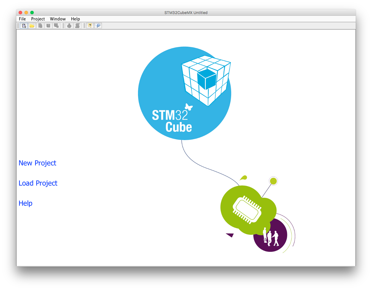
With the collected information, we’re ready to configure the SMT32F4 for this port. Often, we would need to go through the data sheet(s) in detail, but this time, we’re lucky, since ST provides the ST3M2CubeMX tool that helps with this task. It contains all information about the pinout and the clock configuration and can generate working initialization code.
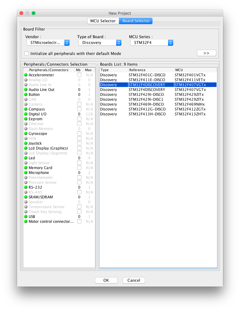
Starting STM32CubeMX, we click “New Project”…
|
… and select the STM32 F4 Discovery board in the Board Selector.
|
Pinout
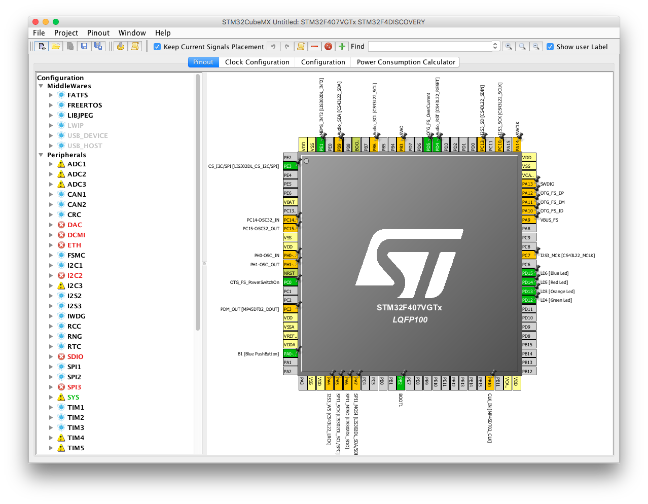
After waiting a few seconds without any kind of progress bar (don’t worry!), we’re in the Pinout configuration.
|
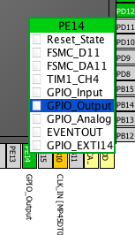
Following our notes, we first configure nShutdown by clicking on PE14 and selecting GPIO_Output.
|
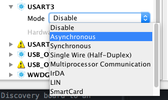
Then, we configure USART 3 as Asynchronous.
|
We also enable Hardware Flow Control.
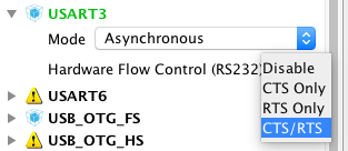
|
Double checking the pinout, we realize that USART3 is not using the pins listed earlier.
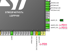
|
We fix the mapping by clicking on the expected pin and selecting the corresponding USART function, here for RX / PD14.
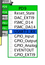
|
While we’re in front of the pinout, we also enable USART2 to use as debug USART – USART2 TX is at Pin PA2 – and arrive at the final pinout.
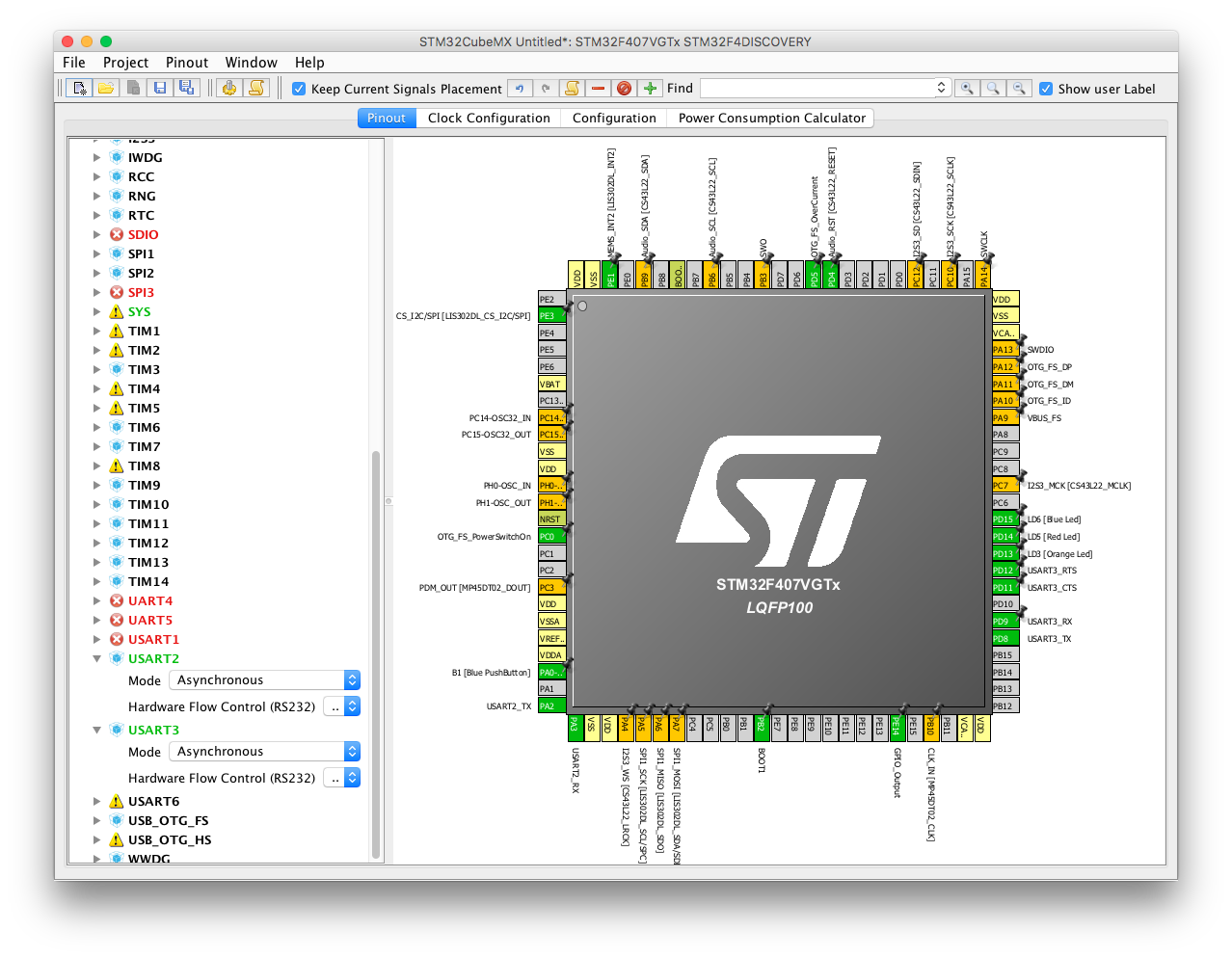
|
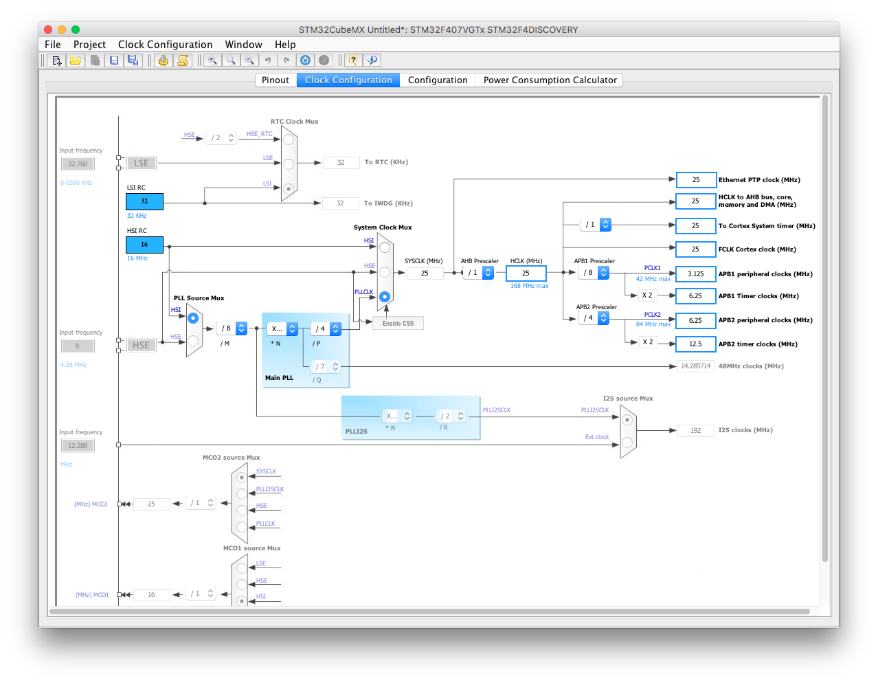
Clock configuration
Next, we’re curious and get fascinated by looking at the clock configuration. For now, we leave it as it is. Spoiler: we’ll need to come back here before the port is complete…
|
Configuration
Clicking on the Configuration tab doesn’t come with much surprises.
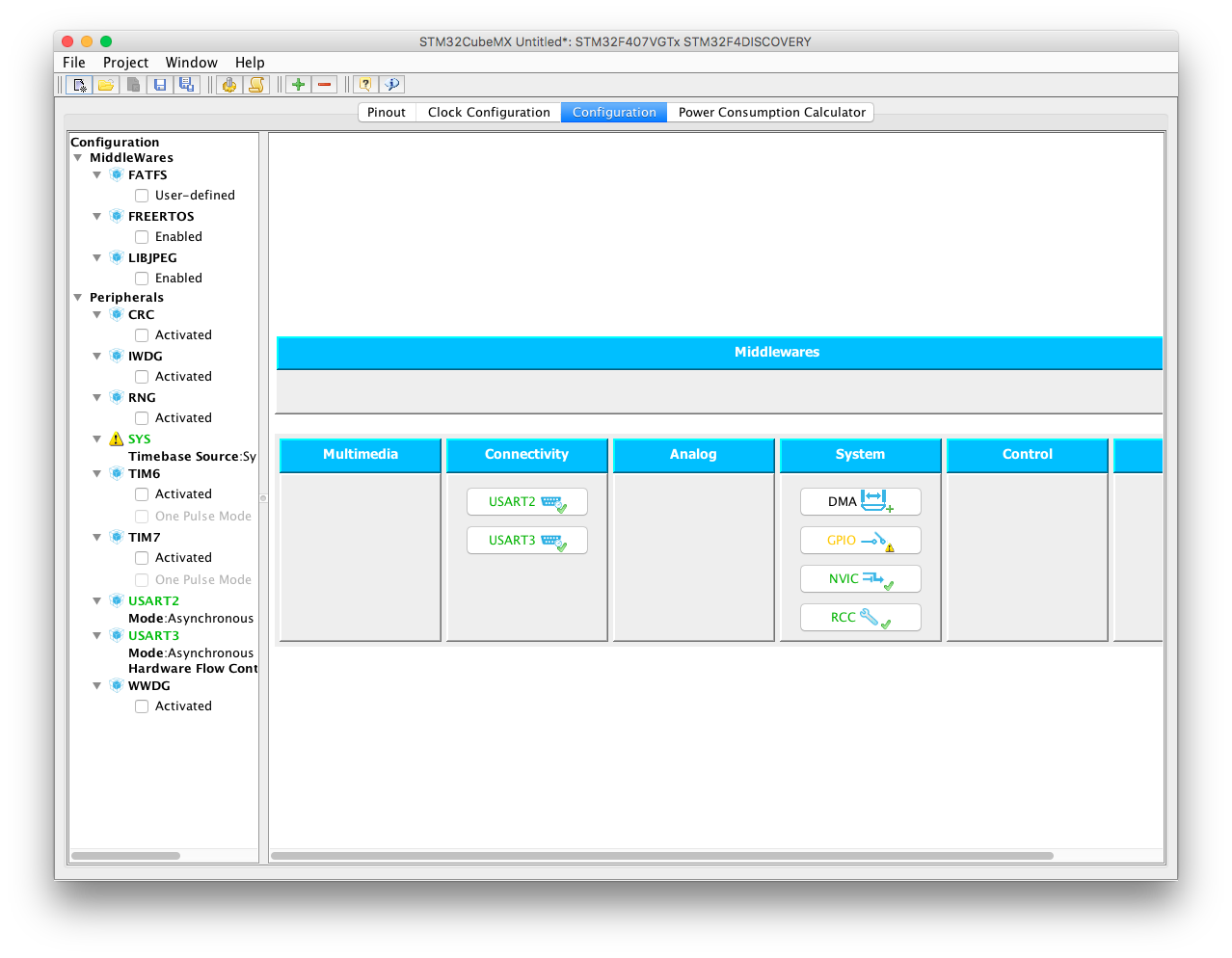
|
However, looking at the shown components, we get motivated to use DMA for the Bluetooth USART.
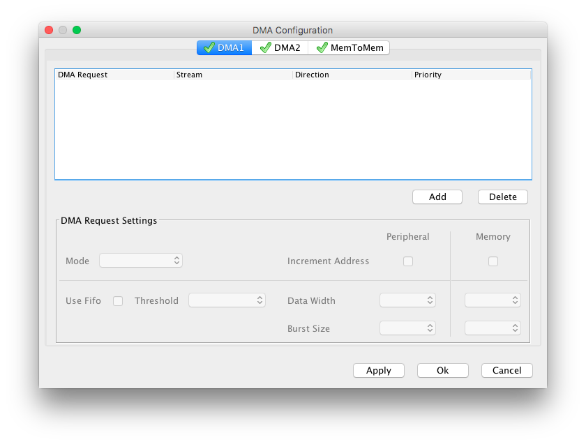
|
We click on on “Add” and select “USART3_RX”, and repeat the same for “USART3_TX”. Finally, we give both Very High priority, because it’s the most important peripheral for us right now.
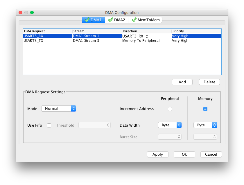
|
Quick check of the Nested Vectored Interrupt Controller (NVIC) doesn’t reveal anything suspicious. The IRQs for the two enabled DMAs are enabled.
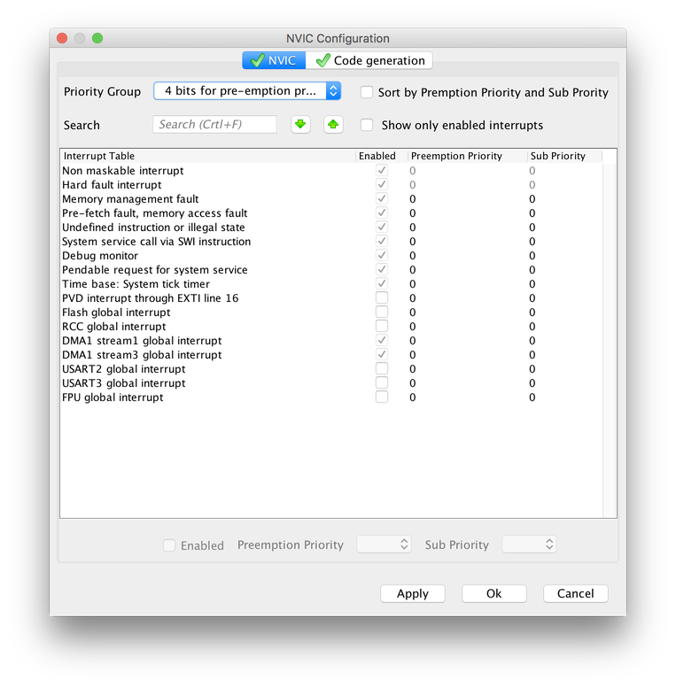
|
Code Generation
After everything is configured, STM32CubeMX can now generate a project for us to continue. Unfortunately, it doesn’t support Eclipse CDT directly, although it supports the SystemWorkbench which is also based on Eclipse. We select SW4STM32 because the CubeMX Importer by Carmine Noviello can import such a project into Eclipse CDT. He is also writing the Mastering STM32 book on the STM32.
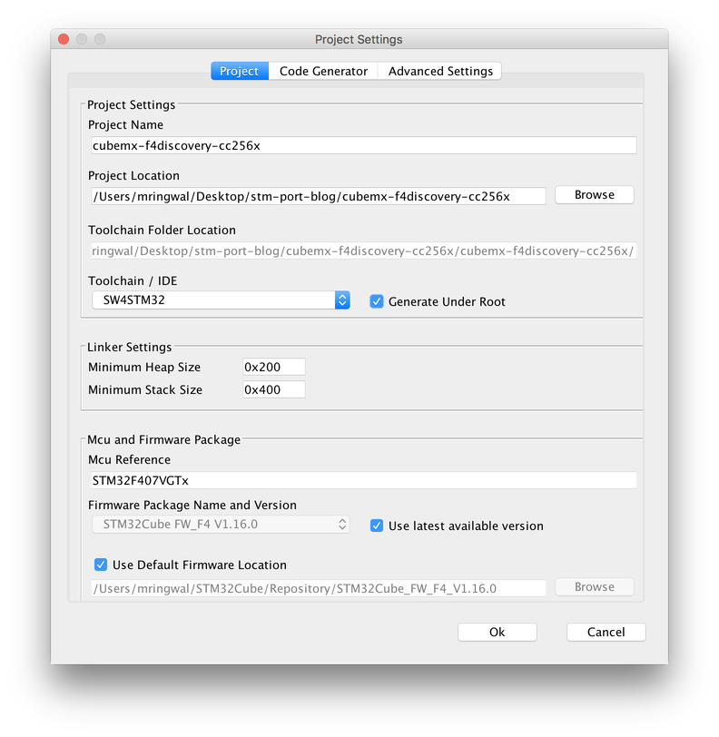
|
In the Code Generator settings, we select Generate peripheral initialization as pair of ‘.c/.h’ files per peripheral as this makes finding the setup code easier.
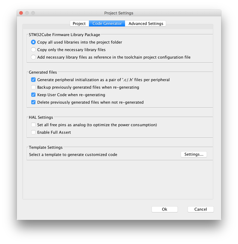
|
After pressing OK, STM32CubeMX generates a folder with all the STMF4xx HAL files, CMSIS, and the custom initialization code (files for CMSIS and HAL not shown).
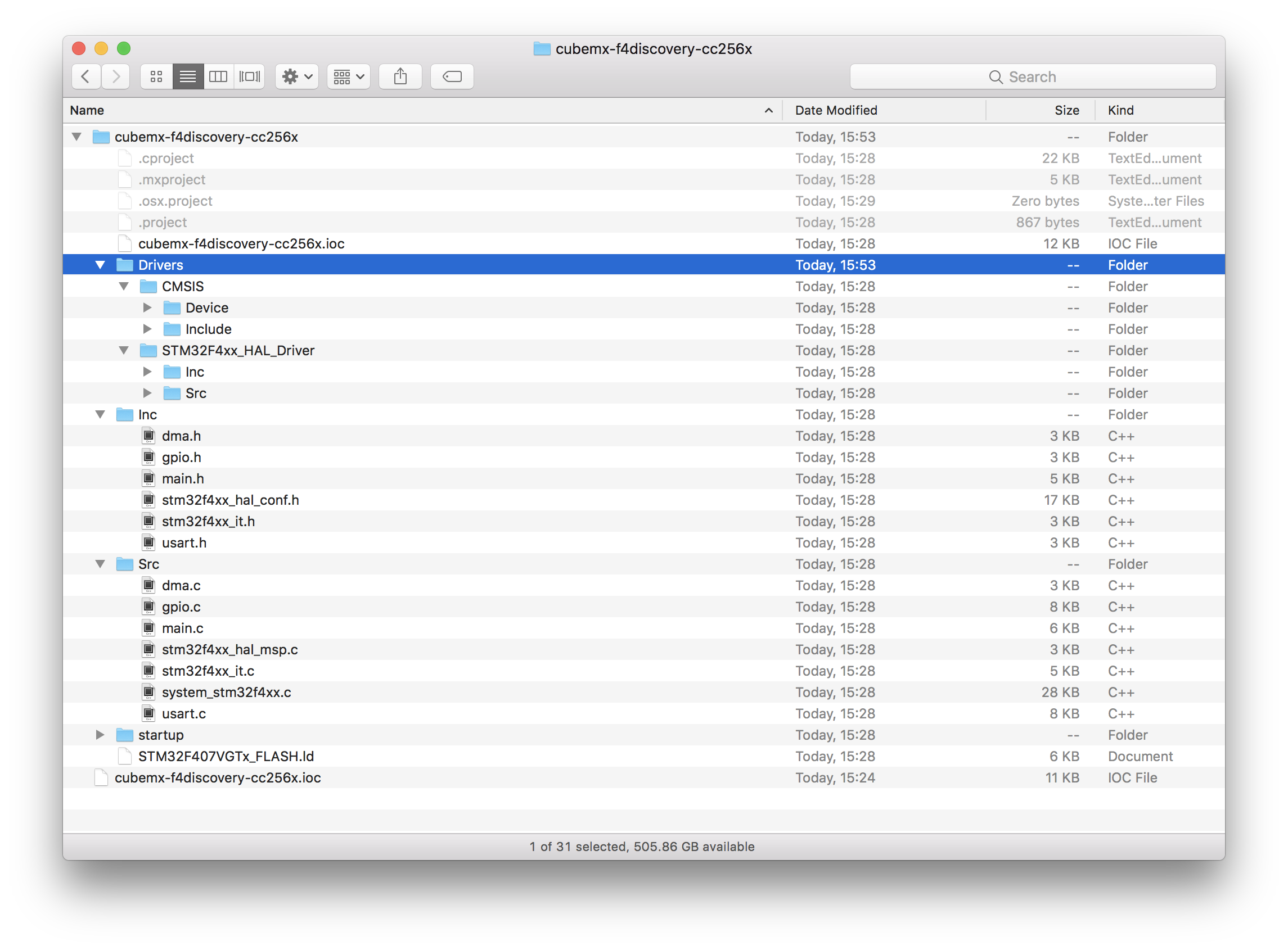
|
Following the CubeMXImporter ReadMe, we now create a new Eclipse C project.
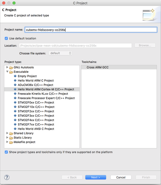
|
The F4 Discovery board has 1024 kB of Flash and 192 kB of RAM. However, the 192 kB are split into 128 kB of general SRAM and 64 kB of Core Coupled Memory (CCM). Entering 192 kB as RAM size prevents the startup, so we just enter 128 kB for now.
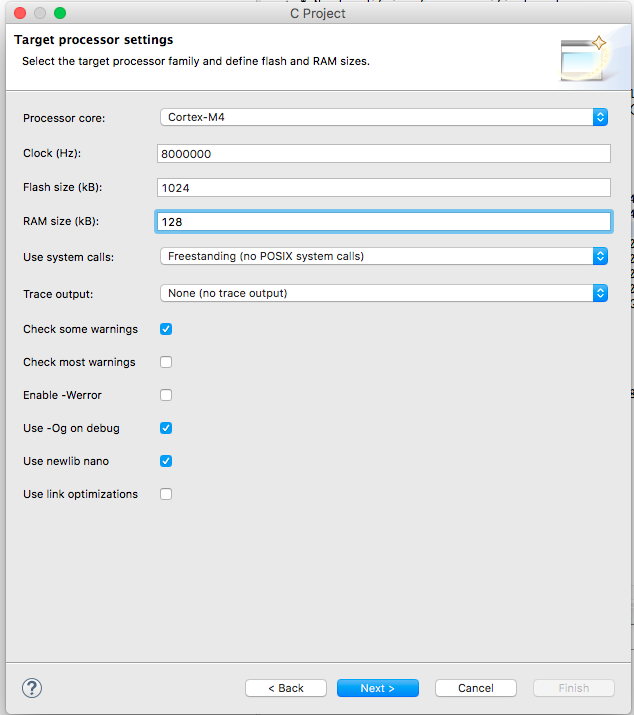
|
And the folder configuration.
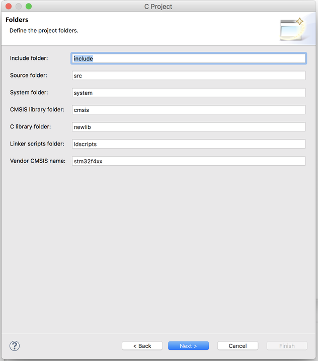
|
Please note that the linker script (ldscripts/mem.ld) of freshly created project places the code at 0x0000000 which makes OpenOCD fail when uploading the code.
Therefore, we skip running the code and just close the project before importing the STM32CubeMX project exported. To import the STM32CubeMX project, run:
$(PATH_TO_CUBEMXIMPORTER)/cubemximporter.py $(PATH_TO_ECLIPSE_PROJECT) $(PATH_TO_EXPORTED_PROJECT)
Now we can go back to Eclipse, open the project and run ‘Refresh’ once more to make it compile. The code is now placed at 0x08000000.
Testing USART2
Although retargetting printf via the debugger works well, we will use USART2 for debug output.
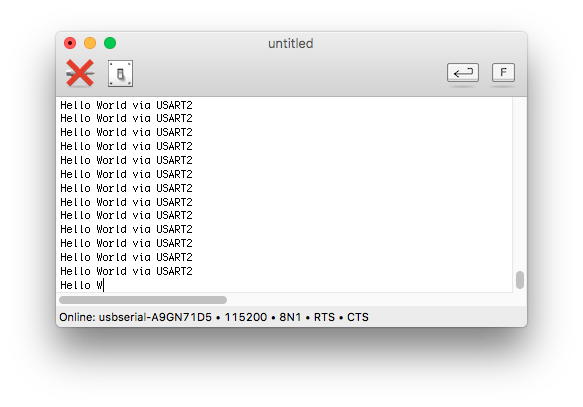
We plug in a USB-2-UART adapter and connect GND and RX of the adapter with PA2 (USART2 TX). Now, it’s time again for some “Hello World”.
In the while loop of main(), we try:
const char * message = "Hello World via USART2\n";
HAL_UART_Transmit(&huart2, message, strlen(message), HAL_MAX_DELAY);
That worked right away and the text shows up in the serial console, great.
|
Retargetting printf
The next step is to redirect printf to use USART2 as well. By default, newlib nano is used. There, you can activate printf by implementing the _write() function that is defined as \__weak__ by the newlib. It also adds a ‘\r’ in front of every ‘\n’.
#include <stdio.h>
#include <unistd.h>
#include <errno.h>

int _write(int file, char *ptr, int len){
    uint8_t cr = '\r';
    if (file == STDOUT_FILENO || file == STDERR_FILENO) {
        int i;
        for (i = 0; i < len; i++) {
            if (ptr[i] == '\n') {
                HAL_UART_Transmit( &huart2, &cr, 1, HAL_MAX_DELAY );
            }
            HAL_UART_Transmit( &huart2, (uint8_t *) &ptr[i], 1, HAL_MAX_DELAY );
        }
        return i;
    }
    errno = EIO;
    return -1;
}
Unfortunately, we also need to implement a number of other functions from newlib, but we get away with returning -1.
int _read(int file, char * ptr, int len){
    (void)(file);
    (void)(ptr);
    (void)(len);
    return -1;
}

int _close(int file){
    (void)(file);
    return -1;
}

int _isatty(int file){
    (void)(file);
    return -1;
}

int _lseek(int file){
    (void)(file);
    return -1;
}

int _fstat(int file){
    (void)(file);
    return -1;
}
Now, we can simplify the code in the main while loop to:
printf("Hello world via printf\n");
Toggle Shutdown
With printf in place, we next try if we can wiggle a pin, more specifically the nShutdown pin PE14. To check if it works, we need an oscilloscope or a logic analyzer.
Setting/clearing a pin is straight forward, after it was configured by STM32CubeMx.
HAL_GPIO_WritePin( GPIOE, GPIO_PIN_14, GPIO_PIN_RESET );
HAL_GPIO_WritePin( GPIOE, GPIO_PIN_14, GPIO_PIN_SET );
Salea’s Logic confirms this. Without doing anything else, we get a 1 Mhz wiggle.
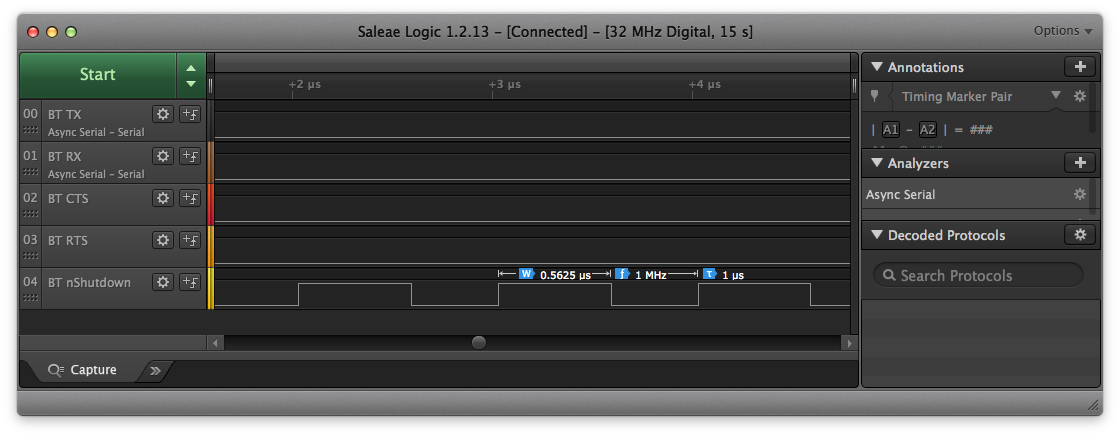
|
In the actual port, we only need to do a simple power cycle like this:
// reset Bluetooth using nShutdown
static void bluetooth_power_cycle(void){
    printf("Bluetooth power cycle\n");
    HAL_GPIO_WritePin( GPIOE, GPIO_PIN_14, GPIO_PIN_RESET );
    HAL_Delay( 250 );
    HAL_GPIO_WritePin( GPIOE, GPIO_PIN_14, GPIO_PIN_SET );
    HAL_Delay( 500 );
}
Since that’s early in the bootup, we just block waiting for the CC256x to boot after reset.
Test USART3 DMA TX
Now, it’s time to talk to the CC256x via DMA. Here is the snippet for this:
HAL_GPIO_WritePin( GPIOE, GPIO_PIN_14, GPIO_PIN_RESET );
HAL_GPIO_WritePin( GPIOE, GPIO_PIN_14, GPIO_PIN_SET );

const uint8_t hci_reset[] = { 0x01, 0x03, 0x0c, 0x00 };
HAL_UART_Transmit_DMA(&huart3, hci_reset, sizeof(hci_reset));
HAL_Delay( 1 );
We expected to get a toggle of the nShutdown and then see a few bytes on USART3 TX, and then it should start over. Instead, we just get a single shot.
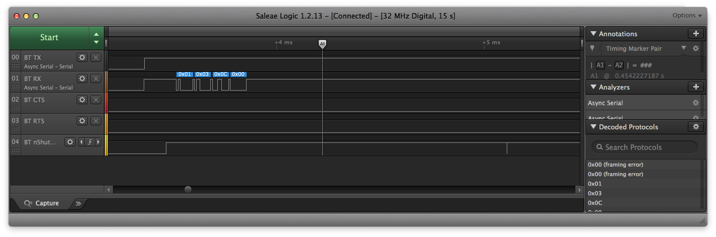
|
It does send the byte sequence for the HCI Reset command, but only once. The main reason for not sending should be that the CC256x RTS / our CTS is up, but that’s not the case. Jumping into the debugger, we see that the state of the USART isn’t HAL_UART_STATE_READY. But why?
Wondering how we would get a callback when the transmission is complete, we learn that we can provide a HAL_UART_TxCpltCallback. A quick test shows that our function isn’t called either. In the HAL code, we see that there are two modes for DMA operation: normal and circular. In normal mode, HAL_UART_TxCpltCallback is called from UART_EndTransmit_IT, which in turn is called by HAL_UART_IRQHandler – the IRQ handler for the UART but we did not enable IRQs for the UART! (since we were planning on using DMA anyway, right?).
Going back to STM32CubeMX, we enable the IRQ for USART3…
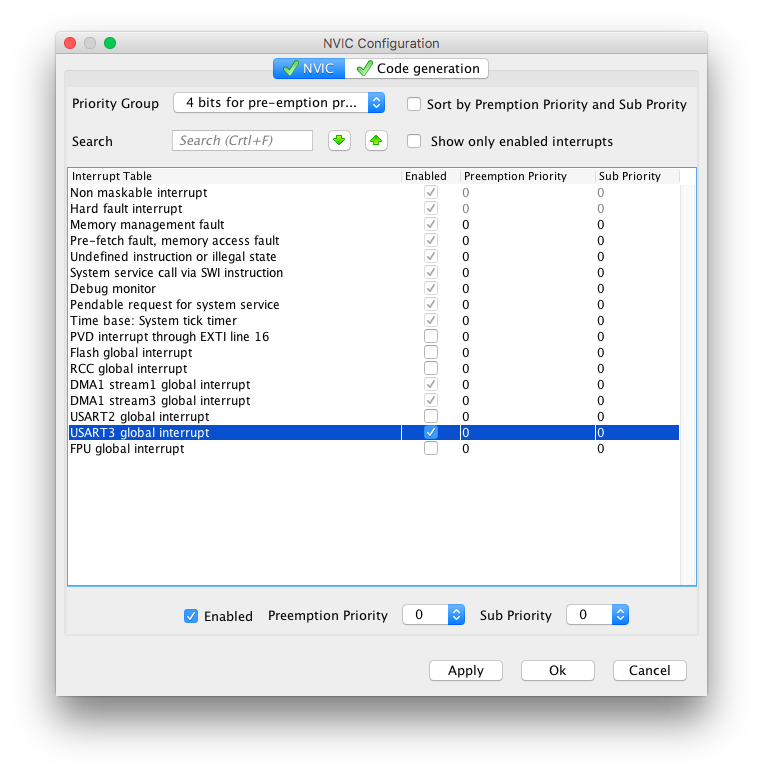
|
.. and regenerate the code, close the project in Eclipse, run CubeMXImporter, re-open the project, click on Refresh, copy our snippet back into main, and try once more. Voila.
|
While we’re already here, we also check if the TX complete callback works by setting tx_done.
volatile int tx_done;
void HAL_UART_TxCpltCallback(UART_HandleTypeDef *huart){
    if (huart == &huart3){
        tx_done = 1;
    }
}
In the main while loop, we wait for this.
HAL_GPIO_WritePin( GPIOE, GPIO_PIN_14, GPIO_PIN_RESET );
HAL_GPIO_WritePin( GPIOE, GPIO_PIN_14, GPIO_PIN_SET );

const uint8_t hci_reset[] = { 0x01, 0x03, 0x0c, 0x00 };
HAL_UART_Transmit_DMA(&huart3, hci_reset, sizeof(hci_reset));

while(!tx_done);
tx_done = 0;
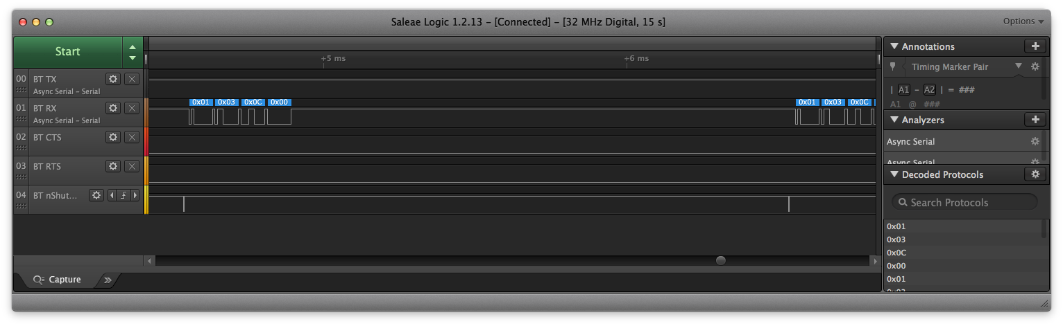
Now, the message is sent over and over, which shows that the TX complete callback works as expected.
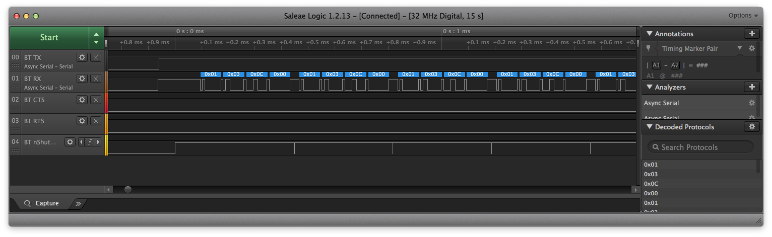
|
HCI Reset
With TX working, we finally plug in the CC256x module and try to send the HCI Reset command to the Bluetooth Controller and await the HCI Command Complete event back.
HAL_GPIO_WritePin( GPIOE, GPIO_PIN_14, GPIO_PIN_RESET );
HAL_Delay( 250 );
HAL_GPIO_WritePin( GPIOE, GPIO_PIN_14, GPIO_PIN_SET );
HAL_Delay( 500 );

const uint8_t hci_reset[] = { 0x01, 0x03, 0x0c, 0x00 };
HAL_UART_Transmit_DMA(&huart3, hci_reset, sizeof(hci_reset));
HAL_Delay( 100 );
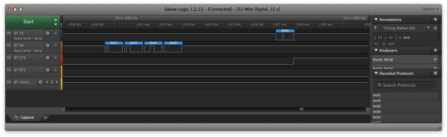
|
Not bad, the first byte is 0x04 (HCI Event Packet Type), but then RX stops, because the UART3 RTS goes up. That’s correct, since we’ve enabled hardware flow control and we didn’t tell the UART / DMA where to put the received data.
We add a single test read call, to receive the expected 7 byte HCI Command Complete Event.
uint8_t event[7];
HAL_UART_Receive_DMA(&huart3, event, sizeof(event));
const uint8_t hci_reset[] = { 0x01, 0x03, 0x0c, 0x00 };
HAL_UART_Transmit_DMA(&huart3, hci_reset, sizeof(hci_reset));
HAL_Delay( 100 );
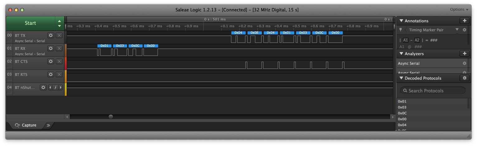
|
Getting Real – Adding BTstack Sources
Now, after checking the hardware and the HAL, we finally can start with BTstack. The easiest way is to clone BTstack with git right into the Eclipse project.
$ cd $(PATH_TO_ECLIPSE_PROJECT)/eclipse-f4discovery-cc256x
$ git clone https://github.com/bluekitchen/btstack.git
Then, press Refresh in Eclipse. There are various sets of sources in BTstack and some are for special platforms like Windows or POSIX. Adding all these to the project will result in many useless compile errors. Instead, we add all relevant source folders and exclude individual files as needed. As the src folder is replaced when using CubeMXImporter to import the STM32CubeMX project, we create an addition port/ folder to keep our sources. We also copy btstack/example/gap_inquiry.c into the port folder as a first test.
| Folder | Description |
|---|---|
| btstack/3rd-party/bluedroid | Sources for SBC Codec used by HFP Wide-Band Speech and A2DP |
| btstack/3rd-party/micro-ecc | micro-ecc used for LE Secure Connections |
| btstack/chipset/cc256x | Support for CC256x chipsets |
| btstack/platform/embedded | Support for Embedded Platform – run loop and HAL |
| btstack/src | BTstack main sources |
| port | Sources for this port |
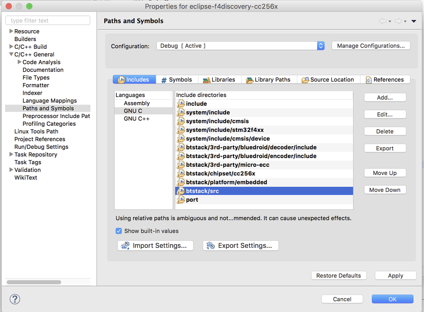
The Sources configuration in Eclipse now looks like this.
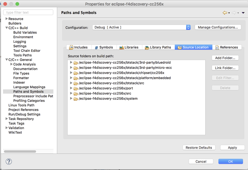
|
We then remove the following individual files or folder:
| Path | Description |
|---|---|
| btstack/src/ble/att_db_util.c | Used to manage GATT DB at run time, requires malloc |
| btstack/3rd-party/micro-ecc/test | Tests require POSIX semantics, not needed in port |
| btstack/platform/embedded/hci_transport_h4_ehcill_embedded.c | Deprecated. We use src/hci_transport_h4.c + platform/embedded/btstack_uart_block_embedded.c instead |
| btstack/platform/embedded/hci_transport_h4_embedded.c | Deprecated. We use src/hci_transport_h4.c + platform/embedded/btstack_uart_block_embedded.c instead |
Of course, we also need to add the corresponding include paths.
| Path | Description |
|---|---|
| btstack/3rd-party/bluedroid/encoder/include | SBC encoder |
| btstack/3rd-party/bluedroid/decoder/include | SBC decoder |
| btstack/3rd-party/micro-ecc | micro-ecc |
| btstack/chipset/cc256x | Support for CC256x chipsets |
| btstack/platform/embedded | Support for Embedded Platform – run loop and HAL |
| btstack/src | BTstack main sources |
| port | Includes for this port |
|
btstack_config.h
Each BTstack port requires the file btstack_config.h that contains the compile-time configuration specific to this port. Since we had an older port for the stm32-f103rb-nucleo, we start with that one and make the following changes: – Replace HAVE_EMBEDDED_TICK with HAVE_EMBEDDED_TIME_MS as the STM32F4xx_hal already provides HAL_GetTick() – Enable LOG_INFO and LOG_ERROR
// btstack_config.h for STM32 F4 Discovery Board + TI CC256B port

#ifndef __BTSTACK_CONFIG
#define __BTSTACK_CONFIG

// Port related features
#define HAVE_EMBEDDED_TIME_MS

// BTstack features that can be enabled
#define ENABLE_BLE
#define ENABLE_LE_PERIPHERAL
#define ENABLE_LE_CENTRAL
#define ENABLE_CLASSIC
#define ENABLE_LOG_INFO
#define ENABLE_LOG_ERROR
// #define ENABLE_EHCILL

// BTstack configuration. buffers, sizes, ...
#define HCI_ACL_PAYLOAD_SIZE 52
#define MAX_SPP_CONNECTIONS 1
#define MAX_NR_GATT_CLIENTS 1
#define MAX_NR_HCI_CONNECTIONS MAX_SPP_CONNECTIONS
#define MAX_NR_L2CAP_SERVICES  2
#define MAX_NR_L2CAP_CHANNELS  (1+MAX_SPP_CONNECTIONS)
#define MAX_NR_RFCOMM_MULTIPLEXERS MAX_SPP_CONNECTIONS
#define MAX_NR_RFCOMM_SERVICES 1
#define MAX_NR_RFCOMM_CHANNELS MAX_SPP_CONNECTIONS
#define MAX_NR_BTSTACK_LINK_KEY_DB_MEMORY_ENTRIES  2
#define MAX_NR_BNEP_SERVICES 0
#define MAX_NR_BNEP_CHANNELS 0
#define MAX_NR_HFP_CONNECTIONS 0
#define MAX_NR_WHITELIST_ENTRIES 1
#define MAX_NR_SM_LOOKUP_ENTRIES 3
#define MAX_NR_SERVICE_RECORD_ITEMS 1
#define MAX_NR_LE_DEVICE_DB_ENTRIES 1

#endif
port.c
As main() gets overwritten each time, we create port.h
#ifndef __PORT_H
#define __PORT_H
void port_main(void);
#endif
and port.c in the port folder and start by adding all includes.
#include "port.h"
#include "btstack.h"
#include "btstack_debug.h"
#include "btstack_chipset_cc256x.h"
#include "btstack_run_loop_embedded.h"
#include "stm32f4xx_hal.h"
Now, we need to implement port_main() that configures BTstack, calls the example setup, and enters the run loop. This code is similar to the main() of other port/xxx/main.c implementations.
// UART configuration
static const hci_transport_config_uart_t config = {
    HCI_TRANSPORT_CONFIG_UART,
    115200,
    0,  // main baud rate = initial baud rate
    1,  // use flow control
    NULL
};

int btstack_main(int argc, const char ** argv);

void port_main(void){
    // init memory pools
    btstack_memory_init();
    // default run loop for embedded systems - classic while loop
    btstack_run_loop_init(btstack_run_loop_embedded_get_instance());
    // enable packet logging, at least while porting
    hci_dump_open( NULL, HCI_DUMP_STDOUT );
    // init HCI
  hci_init(hci_transport_h4_instance(btstack_uart_block_embedded_instance()), (void*) &config);
    // hand over to BTstack example code
  btstack_main(0, NULL);
  // go
  btstack_run_loop_execute();
}
When bravely pressing the build tool, the compile succeeds, but the file size is a bit small
arm-none-eabi-size --format=berkeley "eclipse-f4discovery-cc256x.elf"
   text    data     bss     dec     hex filename
  11631     160     740   12531    30f3 eclipse-f4discovery-cc256x.elf
The reason is that we still need to call port_main() after the init in the main.c:main() function.
#include "port.h"
...
port_main();
The compile errors remind us that we still need to implement a few HALs: – hal_uart_dma.h – hal_cpu.h – hal_time_ms.h
and the printf code from before. We’re adding the printf code back by adding it to the port.c and defining huart2 and huart3 as extern. Let’s start with the simple HALs.
hal_time_ms.h
As mentioned, the setup from STM32CubeMX provides a HAL_GetTick() function that returns the uptime in ms. Our hal_time_ms.h:
#include "hal_time_ms.h"
uint32_t hal_time_ms(void){
    return HAL_GetTick();
}
hal_cpu.h
The functions in hal_cpu allow the run loop to temporarily disable interrupts and put the MCU into sleep. Again, we can use the code from the stm32-f103rb-nucleo port.
// hal_cpu.h implementation
#include "hal_cpu.h"

void hal_cpu_disable_irqs(void){
    __disable_irq();
}

void hal_cpu_enable_irqs(void){
    __enable_irq();
}

void hal_cpu_enable_irqs_and_sleep(void){
    __enable_irq();
    __asm__("wfe"); // go to sleep if event flag isn't set. if set, just clear it. IRQs set event flag
}
hal_uart_dma.h
Since we already managed to do send and receive via DMA, the basic implementation of the hal_uart_dma.h is straight forward. We use a dummy_handler() just in case. For now, we leave the functions to set baud rate (hal_uart_dma_set_baud) or enable wake-up via CTS pulse (hal_uart_set_cts_irq_handler) empty. We’ll take care of that after the stack fully starts up. The init function power cycles the CC256x. Similar to the HAL_UART_TxCpltCallback, there’s also HAL_UART_RxCpltCallback which is called when the requested amount of bytes have been received. In both cases, the registered callback handler is executed.
// hal_uart_dma.c implementation
#include "hal_uart_dma.h"

static void dummy_handler(void);

// handlers
static void (*rx_done_handler)(void) = &dummy_handler;
static void (*tx_done_handler)(void) = &dummy_handler;

static void dummy_handler(void){};

void hal_uart_dma_set_sleep(uint8_t sleep){
    // later..
}

// reset Bluetooth using nShutdown
static void bluetooth_power_cycle(void){
    HAL_GPIO_WritePin( GPIOE, GPIO_PIN_14, GPIO_PIN_RESET );
    HAL_Delay( 250 );
    HAL_GPIO_WritePin( GPIOE, GPIO_PIN_14, GPIO_PIN_SET );
    HAL_Delay( 500 );
}

void HAL_UART_TxCpltCallback(UART_HandleTypeDef *huart){
    if (huart == &huart3){
        (*tx_done_handler)();
    }
}

void HAL_UART_RxCpltCallback(UART_HandleTypeDef *huart){
    if (huart == &huart3){
        (*rx_done_handler)();
    }
}

void hal_uart_dma_init(void){
    bluetooth_power_cycle();
}
void hal_uart_dma_set_block_received( void (*the_block_handler)(void)){
    rx_done_handler = the_block_handler;
}

void hal_uart_dma_set_block_sent( void (*the_block_handler)(void)){
    tx_done_handler = the_block_handler;
}

void hal_uart_dma_set_csr_irq_handler( void (*the_irq_handler)(void)){
    // .. later
}

int  hal_uart_dma_set_baud(uint32_t baud){
    // .. later
    return 0;
}

void hal_uart_dma_send_block(const uint8_t *data, uint16_t size){
    HAL_UART_Transmit_DMA( &huart3, (uint8_t *) data, size);
}

void hal_uart_dma_receive_block(uint8_t *data, uint16_t size){
    HAL_UART_Receive_DMA( &huart3, data, size );
}
With this basic implementation in place, the whole project compiles for the first time.
arm-none-eabi-size --format=berkeley "eclipse-f4discovery-cc256x.elf"
   text    data     bss     dec     hex filename
  36787     192    2620   39599    9aaf eclipse-f4discovery-cc256x.elf
And.. does it work?
[00:00:00.000] LOG -- hci.c.2489: hci_power_control: 1, current mode 0
[00:00:00.760] LOG -- hci.c.3415: BTSTACK_EVENT_STATE 1
[00:00:00.766] EVT <= 60 01 01
[00:00:00.770] CMD => 03 0C 00
[00:00:00.774] EVT <= 6E 00
[00:00:00.777] EVT <= 04 01 03
[00:00:00.781] LOG -- hci.c.1755: Connection_incoming: 00:00:00:00:00:03, type 0
[00:00:00.790] LOG -- hci.c.149: create_connection_for_addr 00:00:00:00:00:03, type fe
[00:00:00.971] LOG -- hci.c.977: Resend HCI Reset
[00:00:00.976] LOG -- hci.c.2935: sending hci_accept_connection_request, remote eSCO 0
A bit, but not really. After the HCI Reset Command (01 03 0C 00), we’re expecting a HCI Command Complete Event but we got 04 04 01 03 (04 is the packet type for HCI event). If we format this, it becomes clear that we’re loosing bytes.
Received: 04 .. 04 01 03 .. ..
Expected: 04 0E 04 01 03 0C 00
BTstack’s HCI Transport H4 implementation issues up to 3 read block requests: 1. to read a single byte with the packet type 2. to read the header dependent on the type. The header has: 3 bytes for HCI Commands and SCO packets, 2 bytes for HCI Events, and 4 bytes for ACL packets. 3. to read the packet payload.
After the first read(1), BTstack issues a read(2). In-between, the 0x0e byte gets lost. Interestingly, we’ve checked that the UART raises the RTS line when its incoming buffer (a single byte) is full. With this in place, we investigate the code for HAL_UART_Receive_DMA of the current STM32F4 HAL version V1.7.1 from 14-April-2017.
HAL_StatusTypeDef HAL_UART_Receive_DMA(UART_HandleTypeDef *huart, uint8_t *pData, uint16_t Size)
{
    ... setup everything that's needed
    /* Clear the Overrun flag just before enabling the DMA Rx request: can be mandatory for the second transfer */
    __HAL_UART_CLEAR_OREFLAG(huart);
    .. start DMA
}
So what does __HAL_UART_CLEAR_OREFLAG(..) do? If it would only clear the overrun flag, no problem. However, it looks like this:
#define __HAL_UART_CLEAR_OREFLAG(__HANDLE__) __HAL_UART_CLEAR_PEFLAG(__HANDLE__)
The idea about clearing only the OREFLAG is already gone. Let’s look at __HAL_UART_CLEAR_PEFLAG then.
#define __HAL_UART_CLEAR_PEFLAG(__HANDLE__)     \
  do{                                           \
    __IO uint32_t tmpreg = 0x00U;               \
    tmpreg = (__HANDLE__)->Instance->SR;        \
    tmpreg = (__HANDLE__)->Instance->DR;        \
    UNUSED(tmpreg);                             \
  } while(0U)
That just reads the status register and the data register, clearing all pending flags etc.. Well, we also just lost the already received byte.
As a quick fix, we remove the call to __HAL_UART_CLEAR_OREFLAG and try again.
[00:00:00.000] LOG -- hci.c.2489: hci_power_control: 1, current mode 0
[00:00:00.760] LOG -- hci.c.3415: BTSTACK_EVENT_STATE 1
[00:00:00.766] EVT <= 60 01 01
[00:00:00.770] CMD => 03 0C 00
[00:00:00.774] EVT <= 6E 00
[00:00:00.778] EVT <= 0E 04 01 03 0C 00
[00:00:00.782] CMD => 01 10 00
[00:00:00.786] EVT <= 6E 00
[00:00:00.791] EVT <= 0E 0C 01 01 10 00 06 00 00 06 0D 00 90 1B
[00:00:00.799] LOG -- hci.c.1689: Manufacturer: 0x000d
[00:00:00.805] CMD => 14 0C 00
[00:00:00.809] EVT <= 6E 00
[00:00:00.835] EVT <= 0E FC 01 14 0C 00 00 00 21 BB 9D 5D F0 F1 AD A2 9D A4 D9 EE B4 7E 42 78 9A 9E DB 9D 55 EC 5D E9 27 33 5C A4 94 5A 6E 8F 48 4F 97 78 25 4A 07 FD 92 72 9E 65 0C 25 EF 5C D8 07 3F 03 54 1B 30 AF CD A7 CC 1B E8 2A A2 D3 28 34 43 55 2A ED AD 0E 5A 45 C4 A6 D9 98 67 46 2A 7C F6 04 2C 9E 71 B4 2D 84 05 9A BC 35 28 3A 86 01 C0 1F 63 54 D5 50 C7 25 1F DE FE 21 06 98 98 A2 E7 73 C3 B2 98 F4 B3 07 CF 90 39 F9 35 7F 64 E5 61 EF 64 3D 9C BF C1 97 26 A1 12 D0 62 5C E6 44 A3 BE FB A4 F2 49 09 06 1D AF 1D 19 AA 2F 36 F5 90 5B EE 88 84 8A 9F 93 F9 B7 A5 FA 45 28 8D 18 60 CA 02 87 D2 00 F8 FD 00 FE 30 CA 0D B5 0B D6 4C 0D E4 19 02 F7 C4 A0 50 19 8D 66 FC 23 98 81 8A 1F 42 0E EB 0C 7C 0E CA 84 0D F9 B5 B9 0E 38 D9 40 14 90 69 AF 6C 91 A5 76 B7 86 D2 98 1A A5 2F 41 35 FC
[00:00:00.927] LOG -- hci.c.1617: local name:
…
And much more output, too long to be useful here. After disabling the packet logger (hci_dump_open), we get:
[00:00:00.000] LOG -- hci.c.2489: hci_power_control: 1, current mode 0
[00:00:00.760] LOG -- hci.c.3415: BTSTACK_EVENT_STATE 1
[00:00:00.769] LOG -- hci.c.1689: Manufacturer: 0x000d
[00:00:00.799] LOG -- hci.c.1617: local name:
[00:00:00.805] LOG -- hci.c.1420: Received local name, need baud change 0
[00:00:00.820] LOG -- hci.c.1697: Local supported commands summary 0x0f
[00:00:00.830] LOG -- hci.c.1658: Local Address, Status: 0x00: Addr: D0:39:72:CD:83:45
[00:00:00.841] LOG -- hci.c.1634: hci_read_buffer_size: ACL size module 1021 -> used 52, count 4 / SCO size 52, count 4
[00:00:00.856] LOG -- hci.c.1678: Packet types 331e, eSCO 1
[00:00:00.863] LOG -- hci.c.1681: BR/EDR support 1, LE support 1
[00:00:00.877] LOG -- hci.c.1224: ---> Name BTstack D0:39:72:CD:83:45
[00:00:00.911] LOG -- hci.c.3527: BTSTACK_EVENT_DISCOVERABLE_ENABLED 0
[00:00:00.920] LOG -- hci.c.1645: hci_le_read_buffer_size: size 27, count 15
[00:00:00.932] LOG -- hci.c.1650: hci_le_read_white_list_size: size 25
[00:00:00.941] LOG -- hci.c.1287: hci_init_done -> HCI_STATE_WORKING
[00:00:00.949] LOG -- hci.c.3415: BTSTACK_EVENT_STATE 2
Starting inquiry scan..
Device found: 5C:F3:70:60:7B:87 with COD: 0x200408, pageScan 1, clock offset 0x690c, rssi 0xd1
Get remote name of 5C:F3:70:60:7B:87...
Failed to get name: page timeout
Starting inquiry scan..
Device found: F4:0F:24:3B:1B:E1 with COD: 0x38010c, pageScan 1, clock offset 0x4227, rssi 0xd4, name 'MBP2016'
Get remote name of 5C:F3:70:60:7B:87...
Almost good. BTstack starts up and the gap_inquiry example starts an inquiry scan. It even finds two device, one is my MacBook, for the second one it cannot get its name.
Init script for CC256x
The reason for the problem getting the remote name is that the CC256x controller like most controllers need to be configured/patched after reboot. BTstack has support for this including the option to control e.g. the transmit power via the code in chipset/cc256x. Before we can activate it, we first need the correct init script and convert it for use with BTstack. The Makefile.inc in chipset/cc256x can be used to automate this process.
cd port
# to get init file for CC2564B
make -f ../btstack/chipset/cc256x/Makefile.inc bluetooth_init_cc2564B_1.5_BT_Spec_4.1.c BTSTACK_ROOT=../btstack
# or, to get init file for CC2564C
# make -f ../btstack/chipset/cc256x/Makefile.inc bluetooth_init_cc2564C_1.0.c BTSTACK_ROOT=../btstack
after Refresh in Eclipse, we select the chipset support for CC256x.
..
hci_init(hci_transport_h4_instance(btstack_uart_block_embedded_instance()), (void*) &config);
hci_set_chipset(btstack_chipset_cc256x_instance());
..
Did it help?
Starting inquiry scan..
Device found: A4:31:35:9D:C4:AC with COD: 0x6a041c, pageScan 1, clock offset 0x113d, rssi 0xc3, name 'iPod Touch 6G Gray'
Device found: 5C:F3:70:60:7B:87 with COD: 0x200408, pageScan 1, clock offset 0x2d52, rssi 0xd4
Device found: F4:0F:24:3B:1B:E1 with COD: 0x38010c, pageScan 1, clock offset 0x0669, rssi 0xd3, name 'MBP2016'
Get remote name of 5C:F3:70:60:7B:87...
Name: 'A2DP Source BTstack'
Yes, it did! Congratulations: BTstack is running on the new hardware with all features supported.
We’re almost at the end of this rather long blog post, but for a complete port, we need to address three more things: .gatt -> .h conversion, baud rate change, and eHCILL Low Power mode.
Example with GATT DB: spp_and_le_counter
Examples with GATT DB are not really different from ones without. BTstack requires to define the GATT DB via a CSV text file with .gatt extension. Getting Eclipse to automatically update the .h from the .gatt file is a bit tedious. For now, we do it by hand when trying to use the spp_and_le_counter example.
$ rm port/gap_inquiry.
$ cp btstack/example/spp_and_le_counter.c port
$ btstack/tool/compile_gatt.py btstack/example/spp_and_le_counter.gatt port/spp_and_le_counter.h

BLE configuration generator for use with BTstack, v0.1
Copyright 2011 Matthias Ringwald

Created port/spp_and_le_counter.h
Compilation successful!
After Eclipse Refresh, the spp_and_le_counter is ready for incoming SPP and LE/GATT connections.
Full Speed & CC256x Flowcontrol Bug
To support higher baudrates than the default 115200 baud, the hal_uart_dma_set_baud(..) needs to be implemented. There’s no direct API for this, but going through the sources reveals that just calling HAL_UART_Init is good enough.
int  hal_uart_dma_set_baud(uint32_t baud){
    huart3.Init.BaudRate = baud;
    HAL_UART_Init(&huart3);
    return 0;
}
Now, the main baud rate can be specified in the UART configuration.
// UART configuration
static const hci_transport_config_uart_t config = {
    HCI_TRANSPORT_CONFIG_UART,
    115200, // initial baud rate
    230400, // main baud rate
    1,  // use flow control
    NULL
};
We enable the packet logger again and give it a try.
[00:00:00.805] CMD => 03 0C 00
[00:00:00.809] EVT <= 6E 00
[00:00:00.813] EVT <= 0E 04 01 03 0C 00
[00:00:00.818] CMD => 01 10 00
[00:00:00.822] EVT <= 6E 00
[00:00:00.826] EVT <= 0E 0C 01 01 10 00 06 00 00 06 0D 00 90 1B
[00:00:00.834] LOG -- hci.c.1689: Manufacturer: 0x000d
[00:00:00.840] CMD => 14 0C 00
[00:00:00.844] EVT <= 6E 00
[00:00:00.870] EVT <= 0E FC 01 14 0C 00 00 00 21 BB 9D 5D F0 F1 AD A2 9D A4 D9 EE B4 7E 10 78 1A 9E DB 9F 55 EC 1D E9 27 33 7C A4 94 5A 6E 8F 48 0F 96 78 25 5A 07 FD 92 72 9F 65 0C 25 EF 5C D8 07 3F 02 54 1B B0 AF ED A7 CC 0B E8 2A A7 D3 28 34 41 55 2A ED AD 2E 58 44 C4 A6 D9 98 77 66 2A 7C F6 14 2C 9E 71 B4 2D 84 05 1A 9C 35 28 3E 86 01 C0 1F 63 54 D5 52 C7 25 1F DE FE 21 86 98 98 E2 E7 F3 C3 32 98 F4 B3 07 CF 90 39 FD 35 7F 6C E5 61 EF 64 3D 9C BF 41 91 26 A3 12 D0 62 5C E6 44 A3 BE FB A4 F2 49 09 06 1D AF 1D 99 AA 0F 36 F5 94 5B EE 8A 84 8A 9F 93 F9 B7 B5 FA 45 38 8D 18 20 CA 02 87 D2 00 F8 FD 00 FE 30 CA 0D B5 0B D6 4E 0D E4 39 02 F7 C4 A0 50 19 8D 66 FC 23 98 80 8A 3F 42 0E EB 0C 7C 0E CA 84 0D E9 B5 B9 0E 2C D9 60 14 90 69 A7 EC 91 A5 77 B7 8E D2 98 1A A5 2F 40 35 FC
[00:00:00.962] LOG -- hci.c.1617: local name:
[00:00:00.967] LOG -- hci.c.1420: Received local name, need baud change 1
[00:00:00.975] CMD => 36 FF 04 00 84 03 00
[00:00:00.981] EVT <= 6E 00
We don’t receive the response to the vendor-specific update UART HCI Baudrate command.
Let’s look at the signal again.
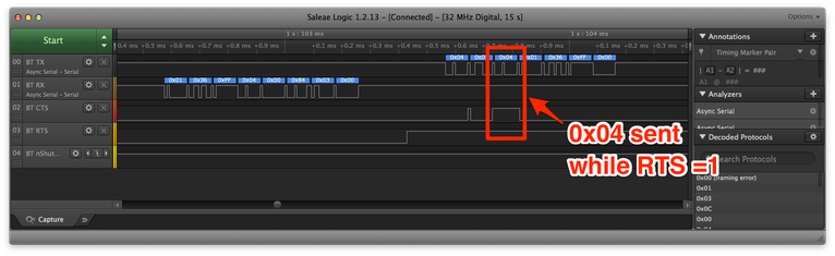
|
The CC256x is sending the third byte of the HCI Command Complete (0x04) although its CTS line is high. Our UART driver will get an overrun error and fail to receive the correct amount of bytes from the UART.
This is a known but undocumented bug of the CC256x series. We had to deal with this before and after evaluating different options, we came up with a fix that does not require hacks in the hal_uart_dma.c implementation – when HCI Transport H4 detects a Bluetooth Controller from TI (‘deep packet inspection’) and sees the Update Baudrate Change Command, it assumes that the Command Complete Event will follow and directly requests 7 bytes from the UART. This fix can be enabled by adding a define to the btstack_config.h:
#define ENABLE_CC256X_BAUDRATE_CHANGE_FLOWCONTROL_BUG_WORKAROUND
From the packet log, we see that we receive the expected response and a look at the logic analyzer confirms this.
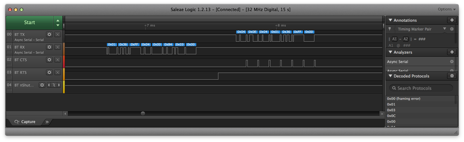
|
However, it gets stuck again sending the next command. The trace is almost correct..
|
.. if the new baudrate would be 230400. Instead, the Start bit of 3.929 ms results in a baud rate of 254 baud.
That’s probably the price for using some HAL instead of going through the data sheet in detail. Doing this now, we learn that the UART can do 8 or 16 times oversampling and uses the PCLK1/ABP1 clock. Going back to the Clock Configuration in the STM32CubeMX tool, we see that ABP1 clock is 3.125 Mhz. Some back-of-the-envelop calculation for the max baud rate at 16 times oversampling: 3.125 Mhz / 16 = 195312.5 baud. This makes sense, 230400 is above this rate and the previous 115200 is within range.
So, we need to configure the clocks differently for a higher baud rate. What’s a good higher baudrate? Well, the maximum supported baud rate is 4 mbps. Let’s aim for this. With 16 times oversampling, we would need 64 Mhz, but the Clock Configuration helpfully shows “42 Mhz max” next to the ABP1 clock. With 8 times oversampling, we would need 32 Mhz, which is below the 42 Mhz max. Now the fun begins. Clicking around (‘explorative learning’), we find that the easiest way is to increase the Main PLL multiplier from x50 to x64, which results in a HCLK of 32 Mhz. We only need to reduce the ABP1 pre-scaler from 8 to 1 to end up with a 32 Mhz ABP1 clock.
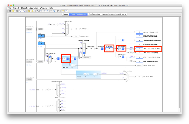
|
We also reduce the 16-times oversampling to 8-times oversampling.
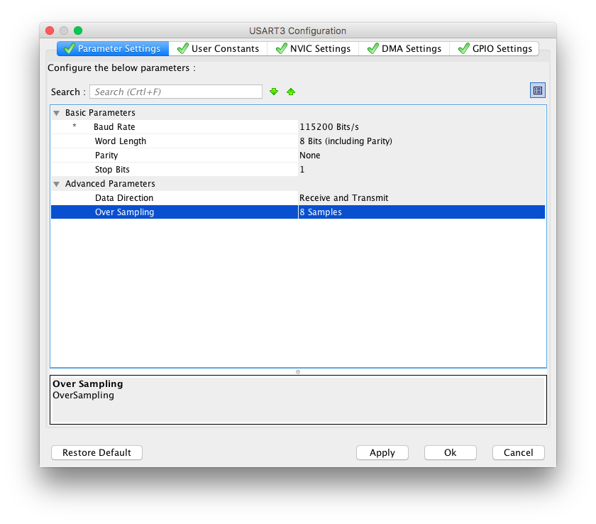
|
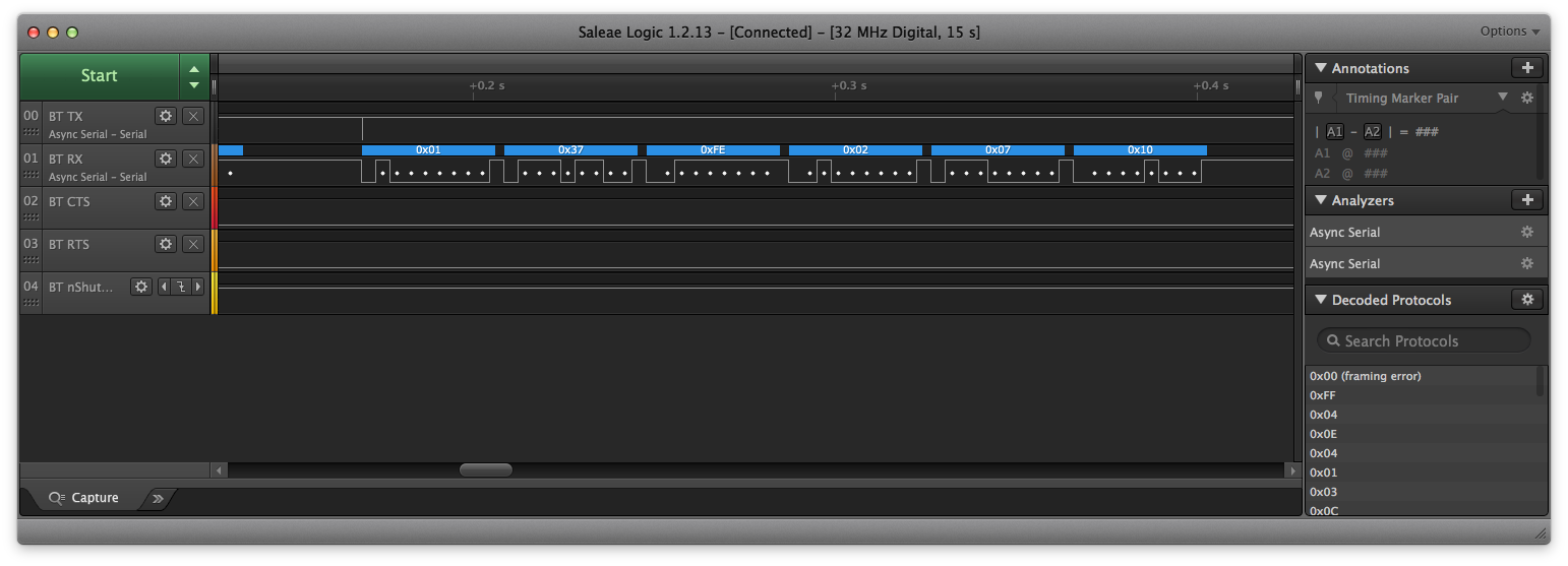
Now.. save CubeMX project, generate sources, close Eclipse project, CubeMXImporter, open Eclipse project, refresh, re-apply patch for HAL_Receive_DMA + jump to port_main() -> BTstack boots up using 4 mbps as main baud rate.
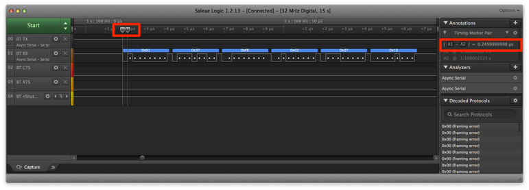
|
Using the marker tools, we confirm that the Start bit has 0.25 us <-> 4 mbps.
Low-Power Modes: eHCILL
Last thing on the list, enabling the eHCILL Low Power Mode.
eHCILL is a proprietary but documented low power mode by Texas Instruments that allows both sides to enter sleep mode and disable the USART (clock) without loosing their synchronization.
BTstack fully supports eHCILL mode. To use it, we first add a define to btstack_config.h
#define ENABLE_EHCILL
This activates eHCILL in the CC256x during startup and adds support for the custom 1-byte message of the eHCILL protocol. This already allows the CC256x to go to sleep when possible and saves energy. For the MCU to also save energy, we need to manually pull RTS high, and to be able to wake up on a CTS pulse.
Pulling RTS high requires to configure PD12 to be GPIO and back to USART when sleep mode is activated.
// state of UART
static int hal_uart_needed_during_sleep;

void hal_uart_dma_set_sleep(uint8_t sleep){
    // RTS is on PD12 - manually set it during sleep
    GPIO_InitTypeDef RTS_InitStruct;
    RTS_InitStruct.Pin = GPIO_PIN_12;
    RTS_InitStruct.Pull = GPIO_NOPULL;
    RTS_InitStruct.Alternate = GPIO_AF7_USART3;
    if (sleep){
        HAL_GPIO_WritePin(GPIOD, GPIO_PIN_12, GPIO_PIN_SET);
        RTS_InitStruct.Mode = GPIO_MODE_OUTPUT_PP;
        RTS_InitStruct.Speed = GPIO_SPEED_FREQ_LOW;
    } else {
        RTS_InitStruct.Mode = GPIO_MODE_AF_PP;
        RTS_InitStruct.Speed = GPIO_SPEED_FREQ_VERY_HIGH;
    }
    HAL_GPIO_Init(GPIOD, &RTS_InitStruct);
    hal_uart_needed_during_sleep = !sleep;
}
When we actually enter MCU sleep mode, the hal_uart_needed_during_sleep indicates if a high speed clock is needed during sleep to receive incoming bytes on the USART.
To get woken up without the USART enabled, CTS needs to be configured as GPIO with external interrupt that triggers on an raising edge. The STM32F4xx series allows to configure external interrupts on all pins and calls the EXTI15_10_IRQHandler for pins 10-15 of each port.
// additional handler
static void (*cts_irq_handler)(void) = &dummy_handler;

void hal_uart_dma_set_csr_irq_handler( void (*the_irq_handler)(void)){

    GPIO_InitTypeDef CTS_InitStruct = {
        .Pin       = GPIO_PIN_11,
        .Mode      = GPIO_MODE_AF_PP,
        .Pull      = GPIO_PULLUP,
        .Speed     = GPIO_SPEED_FREQ_VERY_HIGH,
        .Alternate = GPIO_AF7_USART3,
    };

    if ( the_irq_handler )  {
        /* Configure the EXTI11 interrupt (USART3_CTS is on PD11) */
        HAL_NVIC_EnableIRQ( EXTI15_10_IRQn );
        CTS_InitStruct.Mode = GPIO_MODE_IT_RISING;
        CTS_InitStruct.Pull = GPIO_NOPULL;
        HAL_GPIO_Init( GPIOD, &CTS_InitStruct );
        log_info("enabled CTS irq");
    } else  {
        /* Configure CTS for regular USART operation */
        CTS_InitStruct.Mode = GPIO_MODE_AF_PP;
        CTS_InitStruct.Pull = GPIO_PULLUP;
        HAL_GPIO_Init( GPIOD, &CTS_InitStruct );
        HAL_NVIC_DisableIRQ( EXTI15_10_IRQn );
        log_info("disabled CTS irq");
    }
    cts_irq_handler = the_irq_handler;
}

void EXTI15_10_IRQHandler(void){
    // clear interrupt flag and call handler
    __HAL_GPIO_EXTI_CLEAR_IT(GPIO_PIN_11);
    if (cts_irq_handler){
        (*cts_irq_handler)();
    }
}
Whenever there’s no traffic on the USART, the CC256x triggers sleep mode. Here’s an example of the wake-sequence, caused by an incoming LE connection.
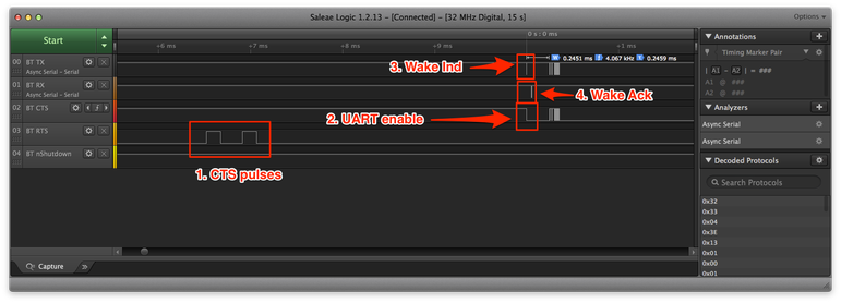
|
Conclusion
So after two days, getting used to new environment and running into one known (CC256x Flow Control) and one unknown bug (STM32F4xx_HAL), we got BTstack happily running on the STM32 F4 Discovery board. We hope that it can serve as a blueprint for other embedded ports.
Of course, this is not hands on tutorial, you can access the eclipse project at btstack/port/stm32-f4discovery-cc256x. We also had fun generating Eclipse project for all examples :).
One more thing for this port: we didn’t use the built-in DAC to play music received by the upcoming A2DP Sink implementation. Other potential topics for this blog are integration with RTOS, especially FreeRTOS, using BTstack with USB Bluetooth Controllers on Embedded Devices, and new Bluetooth controllers.
Update – March 2019
A few months after this post, STMicroelectronics did add an option to STM32CubeMX to generate Makefiles instead of project files for different IDEs. With this, the additional steps using the CubeMXImporter and the additional patching isn’t necessary anymore. We did an update to the F4 Discovery port to directly use Makefiles.
Instead of using Eclipse for programming and debugging, we now use SEGGER Ozone Debugger. If you don’t have a full J-Link programmer, it’s possible to replace the ST-Link v2 on the F4 Discovery board with a SEGGER J-Link OB. This also allows to directly send the console output via the J-Link instead of the UART which requires less resources.